Wideband dual amplifier circuits

A double amplification and circuit technology, applied in amplifiers, amplifier types, superconducting amplifiers, etc., can solve problems such as uneven gain response, poor noise performance, and phase discontinuity

Inactive Publication Date: 2004-02-18
INT BUSINESS MASCH CORP
View PDF0 Cites 3 Cited by
  • Summary
  • Abstract
  • Description
  • Claims
  • Application Information

AI Technical Summary

Problems solved by technology

However, the gain response is not uniform and often phase discontinuous
Also, the noise performance is worse when cascading multiple stages

Method used


Image

  • Wideband dual amplifier circuits
  • Wideband dual amplifier circuits
  • Wideband dual amplifier circuits

Examples


Embodiment Construction

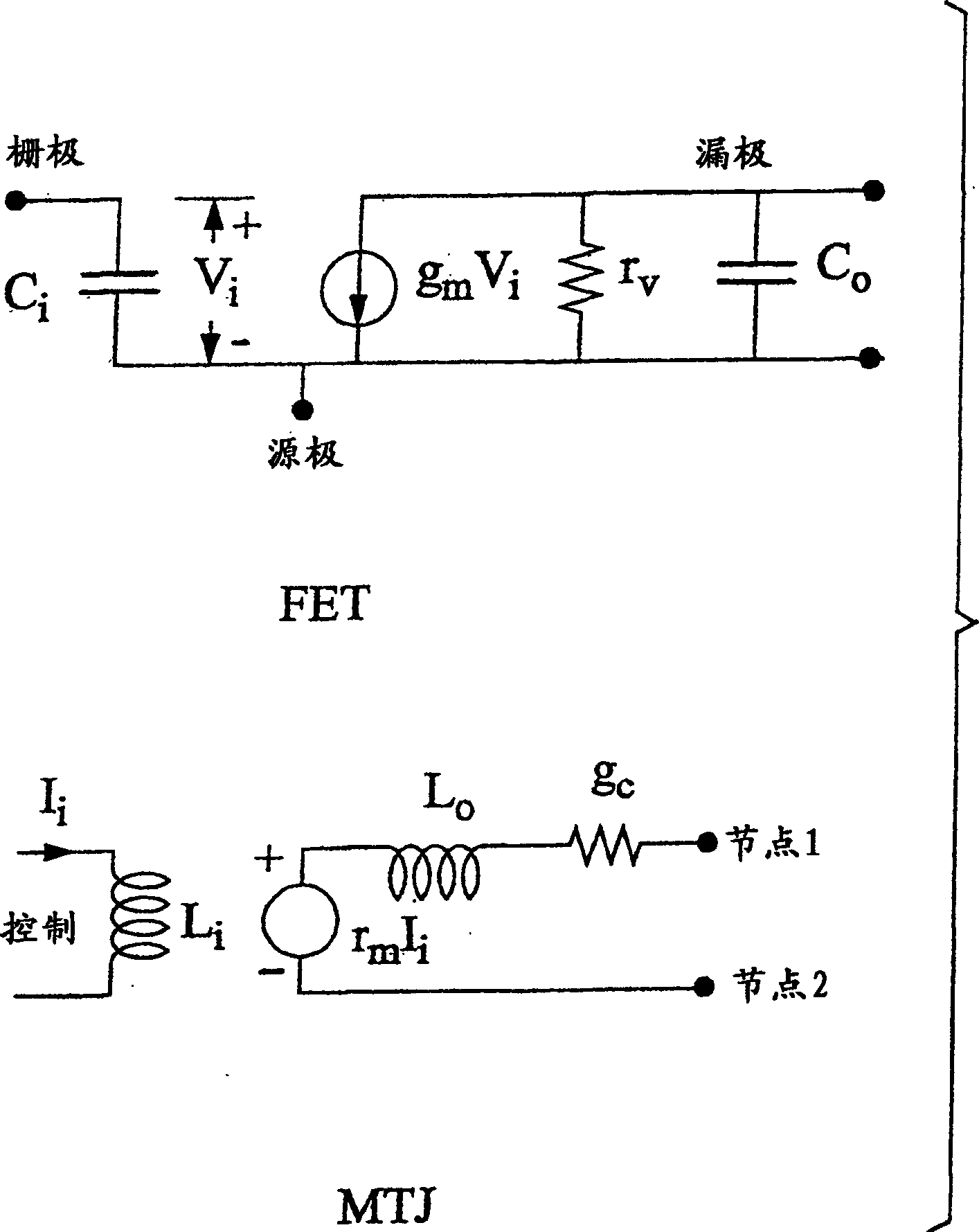
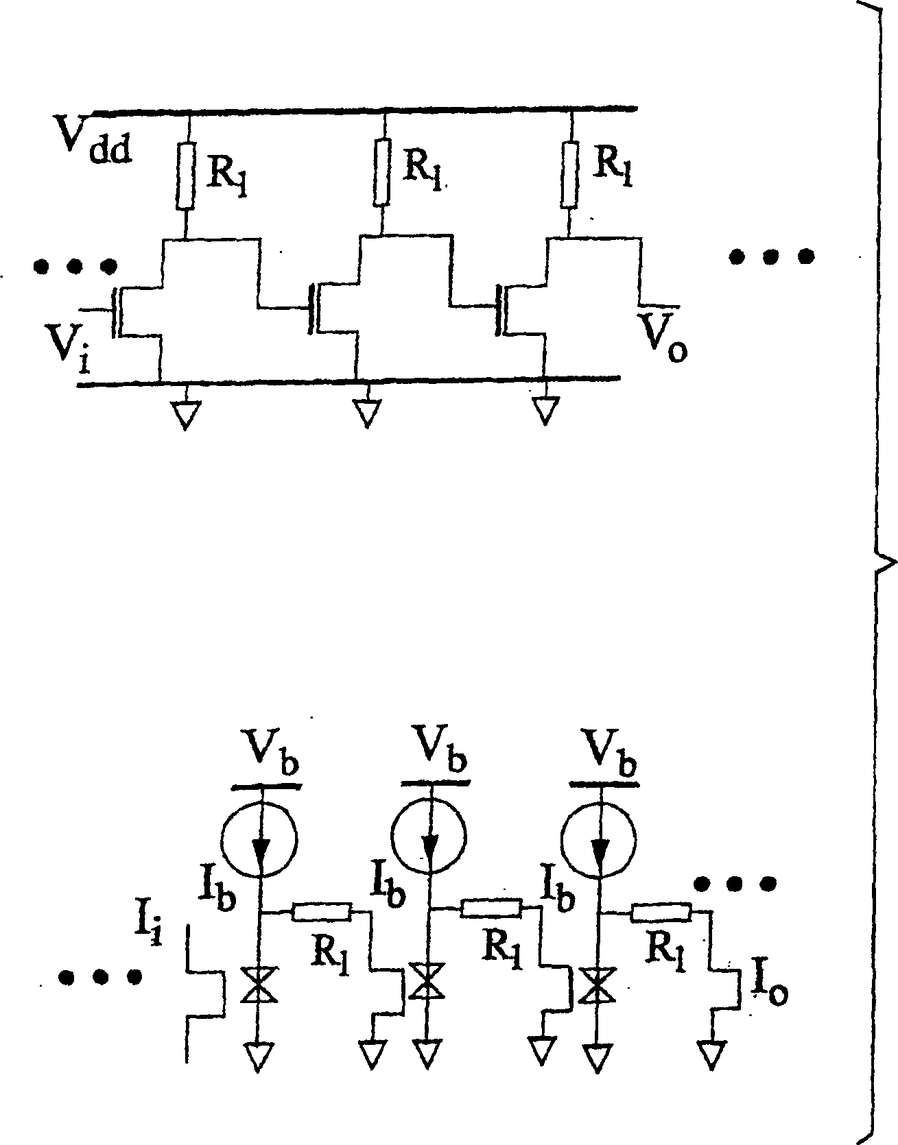
[0017] Two circuits can be considered to be the dual of the other if they obey the same circuit equations but swap the roles of current and voltage. In general, dual circuits were constructed by the parameter / construction exchanges described in Table 1.

[0018] first circuit

second circuit

Current I

Voltage V

Electric field E

Magnetic field M

Resistance R

Inductance G

Inductance L

Capacitance C

Charge Q

Flux Ф

open the way

closed circuit

series connection

parallel connection

node

grid

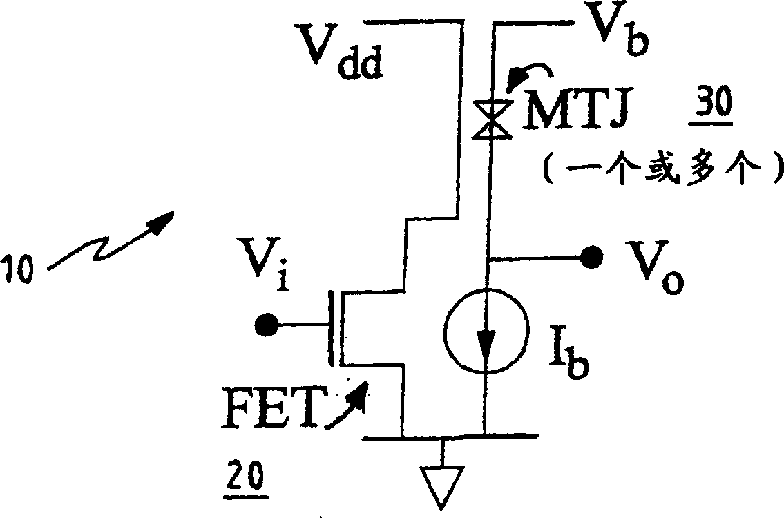
[0019] Semiconductor field effect transistors and magnetic tunnel junctions are similar to active dual elements. FETs are voltage controlled, i.e. the voltage on the gate controls the channel (output) current, the gate has a capacitive impedance, and the different channel impedance is higher - an ideal current source. MTJs are current controlled, i.e. the output voltage is controlled b...


PUM


Abstract

Dual amplifying circuits having a magnetic tunnel junction device and a field effect transistor configured in a complementing set are disclosed herein. In one embodiment, the field effect transistor is operable to control a current level of a current operating signal flowing through the magnetic tunnel junction device. In another embodiment, the magnetic tunnel junction device is operable to control a voltage level of a voltage signal being applied to a gate terminal of the field effect transistor. The gain-bandwidth product of both embodiments is greater than the individual gain-bandwidth products of the individual devices through the elimination of noise contributing resistive type circuit elements.

Description

technical field [0001] In general, the present invention relates to amplifier circuits that provide broadband amplification with minimal noise, and in particular, the present invention relates to amplifier circuits utilizing functionally complementary pairs of devices. Background technique [0002] The gain-bandwidth product and noise figure of a field-effect transistor (hereinafter "FET") limits the ability of the FET to amplify low-level voltage input signals over a large frequency range. Furthermore, the gain-bandwidth product and noise figure of a magnetic tunnel junction device (hereinafter referred to as "MTJ") limits the ability of the MTJ to amplify low-level current input signals over a large frequency range. [0003] In RF and microwave circuits, the gain of an amplifier using a FET or MTJ as an active filter can be increased by narrowing the passband of the FET or MTJ. However, the gain response is not uniform and often phase discontinuous. Also, the noise perfo...

Claims


Application Information

Patent Timeline
Patent Type & Authority Applications(China)
IPC IPC(8): H03F3/193H03F19/00
CPCH03F19/00H03F9/02
Inventor 乌塔姆·高沙尔
Owner INT BUSINESS MASCH CORP
Why Eureka
Try Eureka