Optical information recording medium and its manufacturing method, recording and playback method and device
A technology for recording media and optical information, applied in the manufacture of optical record carriers, optical recording/reproduction/erasing methods, optical record carriers, etc., can solve the problems of large changes in optical characteristics and optical constants, and achieve good recording and playback The effect of the characteristic
- Summary
- Abstract
- Description
- Claims
- Application Information
AI Technical Summary
Problems solved by technology
Method used
Image

Examples
Embodiment 1
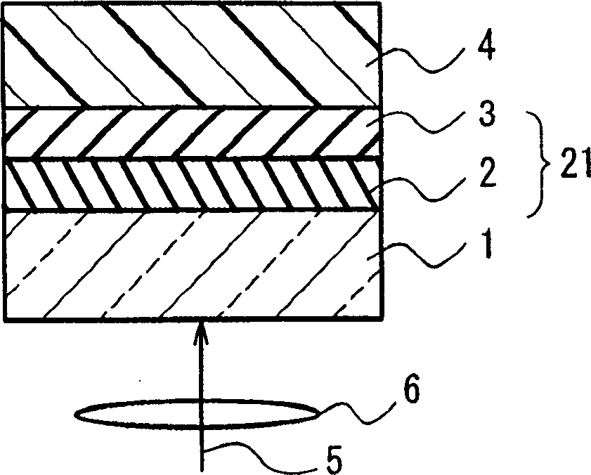
[0086] As the substrate, a substrate made of polycarbonate resin, having a diameter of about 12 cm, a thickness of about 0.6 mm, and a groove pitch of about 0.70 μm and a depth of about 40 nm for laser guiding grooves (groove) was used.
[0087] A ZnS dielectric layer with a film thickness of about 60 nm formed using a ZnS target, and a film formed with a Te-Pd (atomic ratio: 90:10) target were sequentially laminated on the surface of the substrate on which grooves were formed by sputtering. Te-O-Pd recording layer about 40nm thick. Both use a target with a diameter of 100mm and a thickness of about 6mm. The dielectric layer is formed with a 500W RF power supply, and the recording layer is formed with a 100W DC power supply. In addition, the dielectric layer is formed in an atmosphere of Ar only. Ar and O 2 Film formation was performed in an atmosphere of mixed gas (flow ratio 45:55), and the pressure of the atmosphere was kept at 0.2 Pa.
[0088] A dummy substrate was bonde...
Embodiment 2
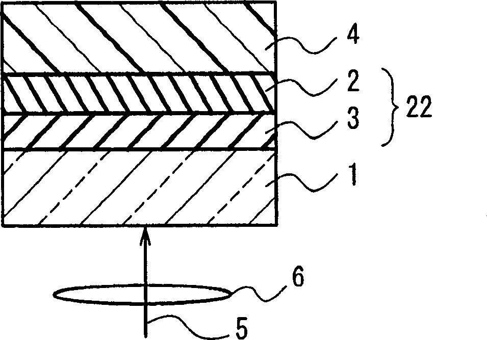
[0095] As the substrate, a substrate made of polycarbonate resin, having a diameter of about 12 cm, a thickness of about 0.58 mm, and a groove pitch of about 0.70 μm and a depth of about 40 nm for laser guiding grooves (groove) was used.
[0096] As the first information layer, a ZnS dielectric layer with a film thickness of about 70 nm was formed using a ZnS target, and a Te-Pd (atomic ratio: 90:10 ) target to form a Te-O-Pd recording layer with a film thickness of about 20 nm. In addition, as the second information layer, a Te-Pd (atomic ratio: 90:10) target with a film thickness of about 40 nm was sequentially laminated on the surface of another same substrate on which grooves were formed by the sputtering method. -O-Pd recording layer, and a ZnS dielectric layer with a film thickness of about 60 nm formed using a ZnS target. Both use a target with a diameter of 100mm and a thickness of about 6mm. The dielectric layer is formed with a 500W RF power supply, and the recordin...
Embodiment 3
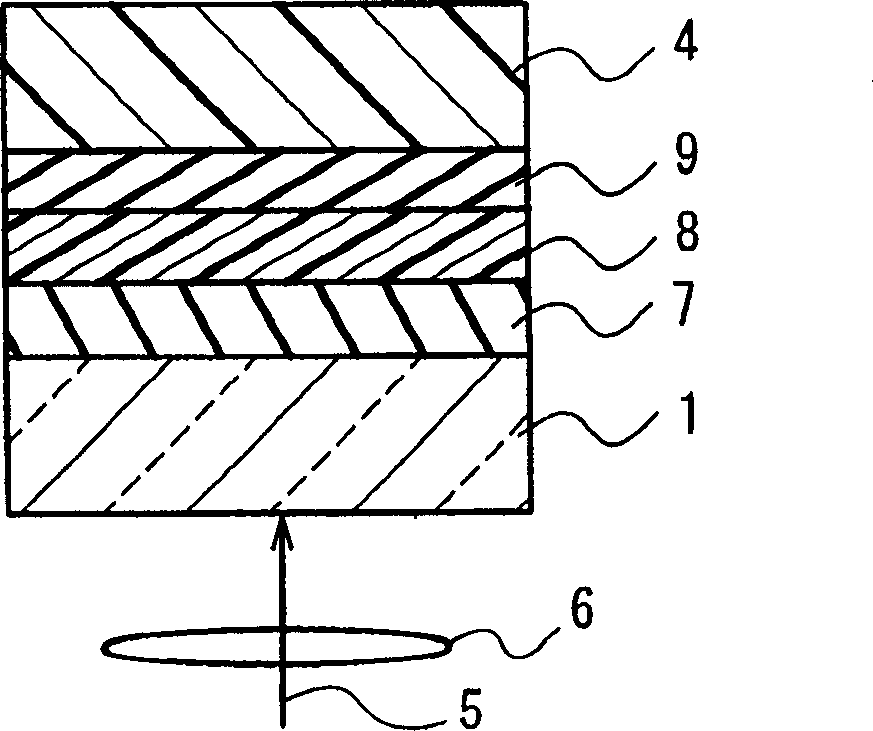
[0102] Figure 7 It is a cross-sectional view of an optical information recording medium in Example 3 of the present invention.
[0103] As the protective layer 4, a polycarbonate resin substrate having a diameter of about 12 cm, a thickness of about 1.1 mm, and a groove pitch of about 0.32 μm and a depth of about 30 nm for laser guidance was used.
[0104] As the fourth information layer 34, Te-O with a film thickness of about 40 nm was sequentially laminated on the surface of the protective layer 4 on which grooves were formed by sputtering using a Te-Pd (atomic ratio: 90:10) target. - The Pd recording layer and the ZnS dielectric layer with a film thickness of about 60 nm were formed using a ZnS target. The same groove pattern as that of the protective layer was replicated on the surface of the fourth information layer 34 by 2P (photopolymerization) using an ultraviolet curable resin to form a separation layer 8c having a thickness of about 10 micrometers. As the third in...
PUM
| Property | Measurement | Unit |
|---|---|---|
| wavelength | aaaaa | aaaaa |
| thickness | aaaaa | aaaaa |
| thickness | aaaaa | aaaaa |
Abstract
Description
Claims
Application Information
 - R&D
- Intellectual Property
- Life Sciences
- Materials
- Tech Scout
- Unparalleled Data Quality
- Higher Quality Content
- 60% Fewer Hallucinations
Browse by: Latest US Patents, China's latest patents, Technical Efficacy Thesaurus, Application Domain, Technology Topic, Popular Technical Reports.
© 2025 PatSnap. All rights reserved.Legal|Privacy policy|Modern Slavery Act Transparency Statement|Sitemap|About US| Contact US: help@patsnap.com