Laminate with an electrically conductive layer formed as an antenna structure

A technology of antenna structure and conductive layer, applied in antennas, loop antennas, antenna parts and other directions, can solve the problem of high cost of antennas

Inactive Publication Date: 2004-03-17
INFINEON TECH AG
View PDF0 Cites 7 Cited by
  • Summary
  • Abstract
  • Description
  • Claims
  • Application Information

AI Technical Summary

Problems solved by technology

[0014] These methods are too costly for the manufacture of antennas suitable for the applications described above

Method used


Image

  • Laminate with an electrically conductive layer formed as an antenna structure
  • Laminate with an electrically conductive layer formed as an antenna structure
  • Laminate with an electrically conductive layer formed as an antenna structure

Examples


Embodiment Construction

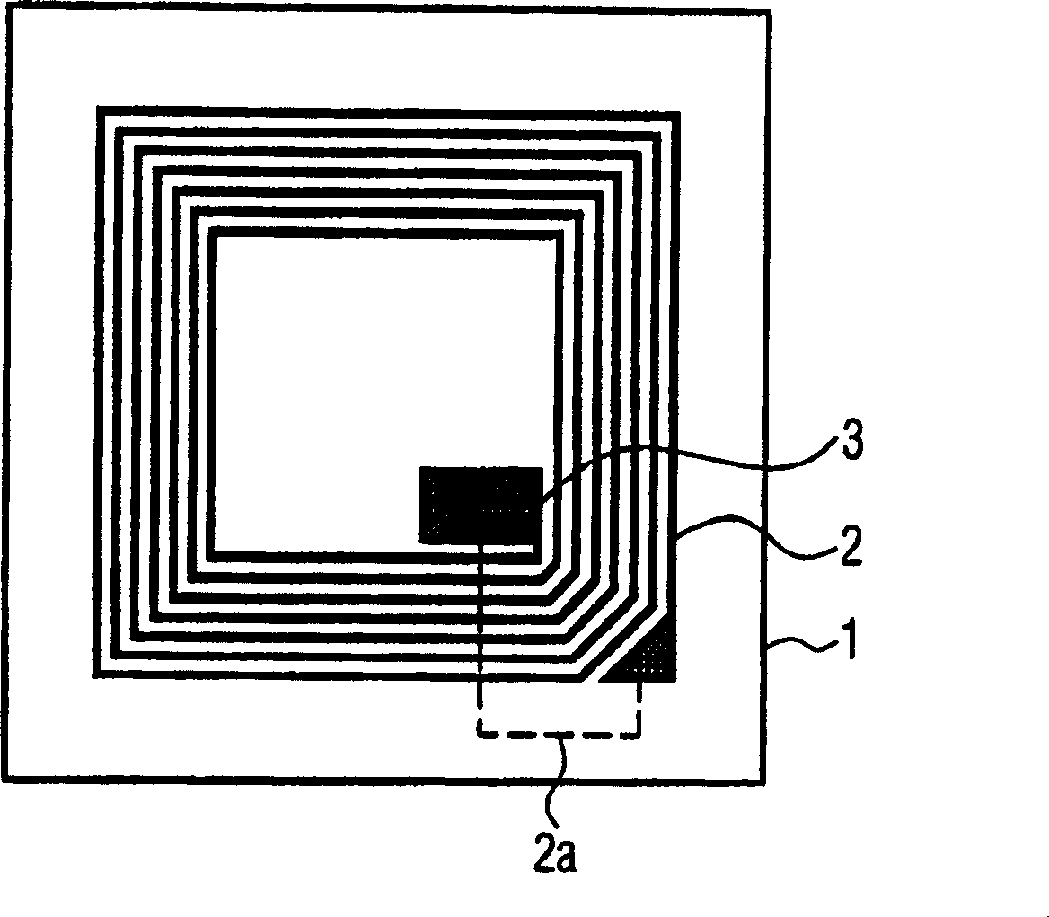
[0068] figure 1 Denotes a radiation identification tag according to known art. The antenna structure produced from several coils is applied to a flexible film 1 which is used as a carrier layer. The ends of the antenna structure 2 are conductively connected to a silicon microchip 3 . Both ends of the antenna structure are connected to each other via a bridge structure 2a. The rear side of the carrier layer 1 may be provided with an adhesive layer in order to be able to fix the label to the object to be identified, eg a file. The antenna structure 2 is first manufactured independently and then fixed to the membrane 1 . The manufacture of such labels is therefore complicated.

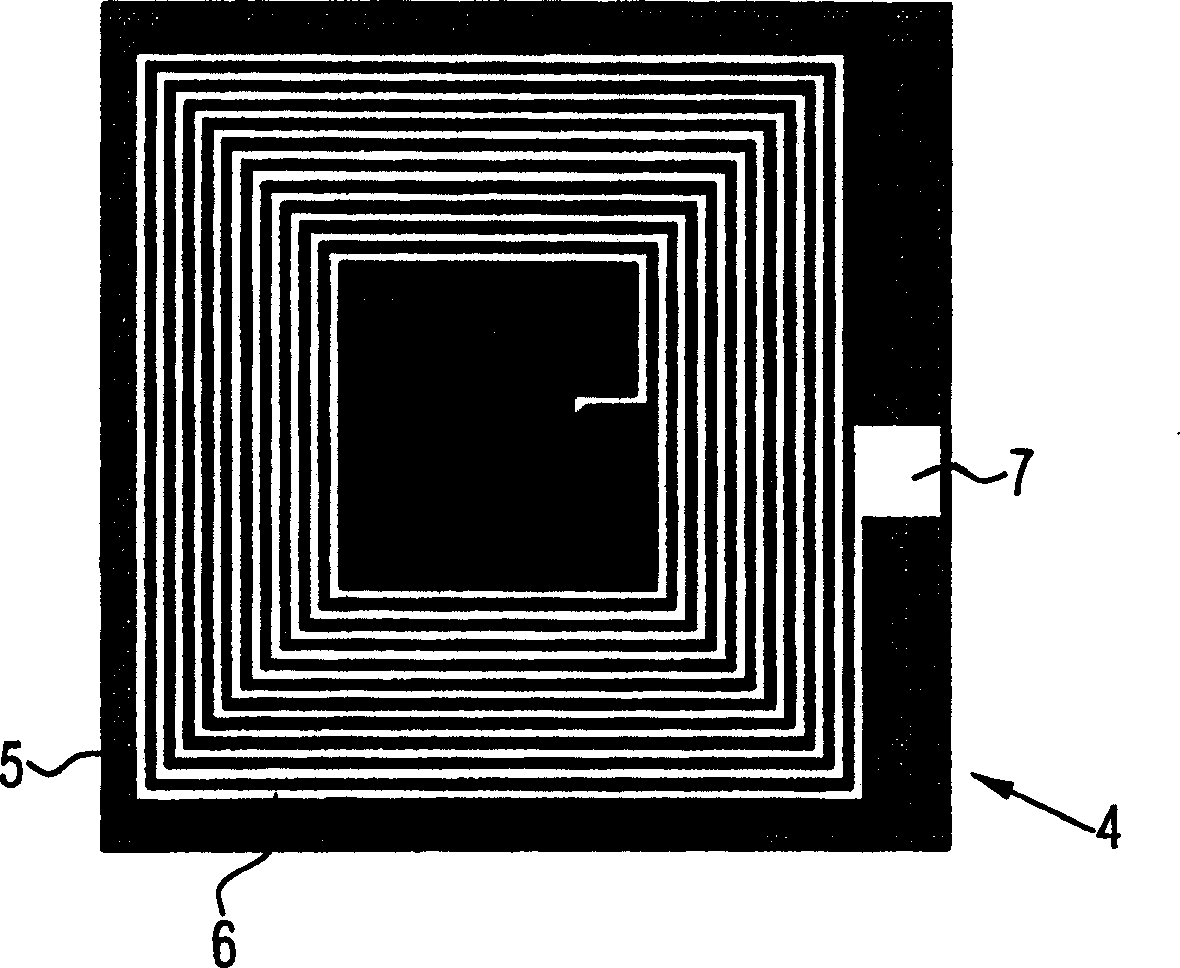
[0069] figure 2 Shown is a mask 4 that can be used in the fabrication of an antenna structure for the ply of the invention. This mask 4 includes shaded areas 5, which are shown in black in the figure. Also introduced into the mask are helical openings 6 shown in white. The openings 6 correspond t...


PUM

PropertyMeasurementUnit
thicknessaaaaaaaaaa

Abstract

A laminate is formed from a carrier layer and an electrically conductive layer. In one section, the conductive layer is formed into an antenna structure. The antenna structure can be produced in a joint operation with the electrically conductive layer. The antenna structure is connected to a microchip, so that data can be written in or read out without contact in a wireless transponder system.

Description

technical field [0001] The invention relates to a laminate comprising a carrier layer and a conductive layer. Such plies are used, for example, in the manufacture of beverage cartons. Background technique [0002] Transponder technology allows data to be read from and stored in a microchip without contact. For this purpose, this microchip is connected to an antenna with which the electromagnetic radiation to be written into or read out from the microchip can be received and emitted. Using an external transmitter the transmitter and receiver unit can communicate with the microchip via electromagnetic radiation. In this case, the microchip usually does not contain its own power supply, so the radiation used to write to and read from the microchip is also used to provide the power supply for the microchip. [0003] The technologies used for this purpose have so far not been able to be manufactured below a certain cost framework. For this reason, current corresponding device...

Claims


Application Information

Patent Timeline
Patent Type & Authority Applications(China)
IPC IPC(8): B32B15/20B65D5/42G06K19/077H01Q1/22H01Q7/00
CPCB65D5/4233H01Q7/00H01Q1/22H01Q1/2225B65D2203/10G06K19/07783G06K19/07749G06K19/07779G06K19/0776B32B15/20Y10T29/49016Y10T29/49018Y10T29/4913Y10T156/1062Y10T428/13Y10T428/24917B32B15/08B32B2439/70
Inventor G·施米德H·克劳克M·哈里克
Owner INFINEON TECH AG
Why Eureka
Try Eureka