Image signal process device

A technology of image signal processing and image signal, which is applied in the direction of image communication, TV, color TV parts, etc., and can solve problems such as clamp instability and noise

Inactive Publication Date: 2004-03-24
SANYO ELECTRIC CO LTD
View PDF0 Cites 1 Cited by
  • Summary
  • Abstract
  • Description
  • Claims
  • Application Information

AI Technical Summary

Problems solved by technology

Therefore, when the gain is increased, the clamp becomes unstabl...

Method used


Image

  • Image signal process device
  • Image signal process device
  • Image signal process device

Examples


Embodiment Construction

[0021] Next, embodiments of the present invention will be described with reference to the drawings.

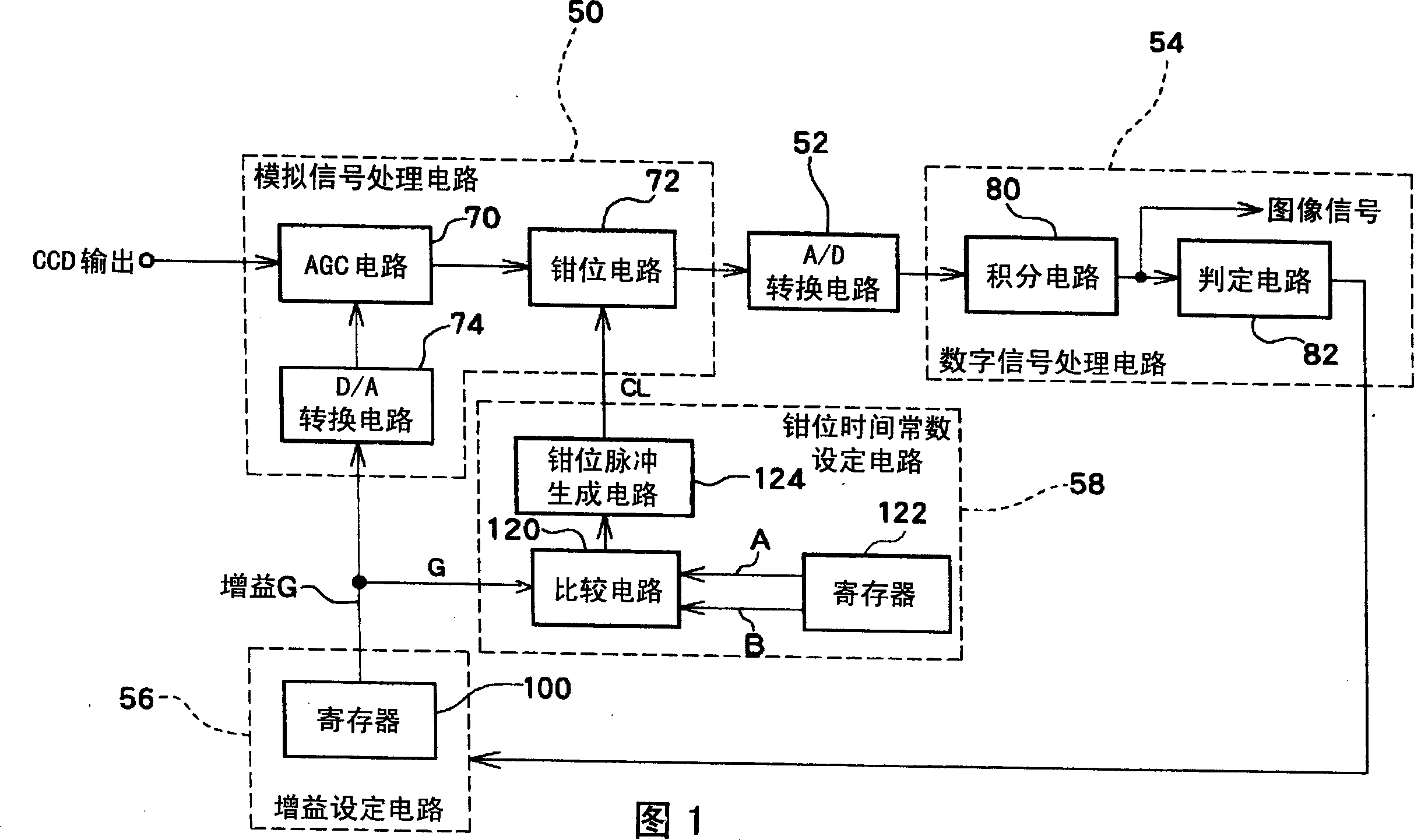
[0022] FIG. 1 is a block diagram showing a schematic circuit configuration of an image signal processing device according to an embodiment of the present invention. This device is composed of an analog signal processing circuit 50 , an A / D (Analog-to-Digital) conversion circuit 52 , a digital signal processing circuit 54 , a gain setting circuit 56 , and a clamp time constant setting circuit 58 .

[0023] The analog signal processing circuit 50 includes an AGC circuit 70 , a clamp circuit 72 , and a D / A (Digital-to-Analog) conversion circuit 74 . The AGC circuit 70 inputs an image signal from the CCD image sensor, and amplifies that image signal in accordance with the gain given from the gain setting circuit 56 . The clamp circuit 72 is a circuit that clamps the DC level of the image signal amplified on the AGC circuit 70, and is synchronized with the horizontal synchronizati...


PUM


Abstract

An AGC circuit (70) amplifies a video signal according to again value output from again setting circuit (56). A clamp circuit (72) performs clamping of the direct current level of an output signal from the AGC circuit (70) at a clamp ability level according to a time constant set by a clamp time constant setting circuit (58). The clamp time constant setting circuit (58) receives input of the gain value generated by the gain setting circuit (56). A comparator circuit (120) compares the received gain value to a reference value, and, when the gain value exceeds the reference value, outputs a relatively large time constant. The clamp ability level of the clamp circuit (72) is controlled according to this time constant. In this manner, when the gain value is large, gradual clamping can be executed so as to minimize the influence of noise components superimposed on the direct current level, thereby suppressing transverse noise.

Description

technical field [0001] The present invention relates to an image signal processing device for processing an image signal output from an imaging element, and particularly relates to control of the DC level of the image signal. Background technique [0002] An image signal obtained by an imaging element such as a CCD (Charge Coupled Device) image sensor is usually taken out by capacitive coupling. Therefore, the DC level of the image signal can be varied by the image signal level. Therefore, an image signal (OPB image signal) corresponding to an optical black area (OPB) provided in the peripheral portion of the pixel array of the imaging element is subjected to clamping processing for setting a predetermined black level. Furthermore, in the output of an AGC (Auto Gain Control) circuit provided in the subsequent stage, the DC level of the image signal can be varied according to the gain of the AGC circuit. Therefore, a clamping circuit for controlling the DC level is provided...

Claims


Application Information

Patent Timeline
IPC IPC(8): H04N5/18
CPCH04N5/185H04N5/18
Inventor 高桥达也渡边透田畑修
Owner SANYO ELECTRIC CO LTD
Why Eureka
Try Eureka