Air conditioner
A technology of air-conditioning device and driving device, applied in the direction of output power conversion device, transportation and packaging, air treatment equipment, etc.
- Summary
- Abstract
- Description
- Claims
- Application Information
AI Technical Summary
Problems solved by technology
Method used
Image

Examples
Embodiment approach 1
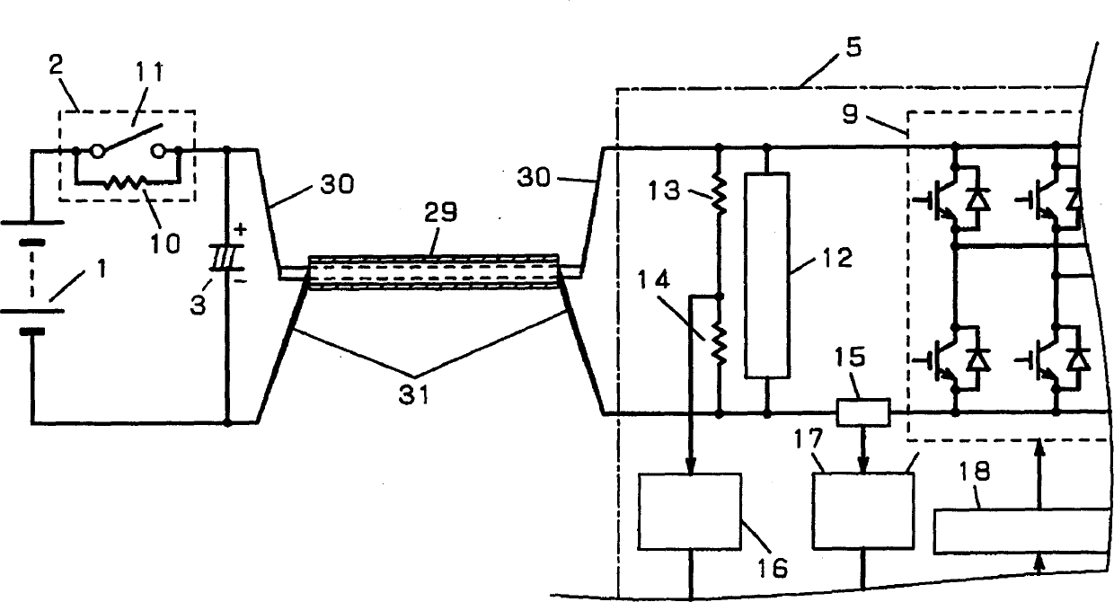
[0065] FIG. 1 shows a circuit diagram of an electric compressor drive unit. The difference from FIG. 17 which is a conventional example is that the power lead wire is changed to one shielded wire 29, and the electrolytic capacitor 41 is eliminated, but the electrolytic capacitor 3 is provided on the battery 1 side.
[0066] This electrolytic capacitor 3 is unnecessary if the source impedance of the battery 1 is very low. In addition, in the shielded wire 29, the core wire 30 is set to the positive side, and the outer peripheral wire 31 is set to the negative side.
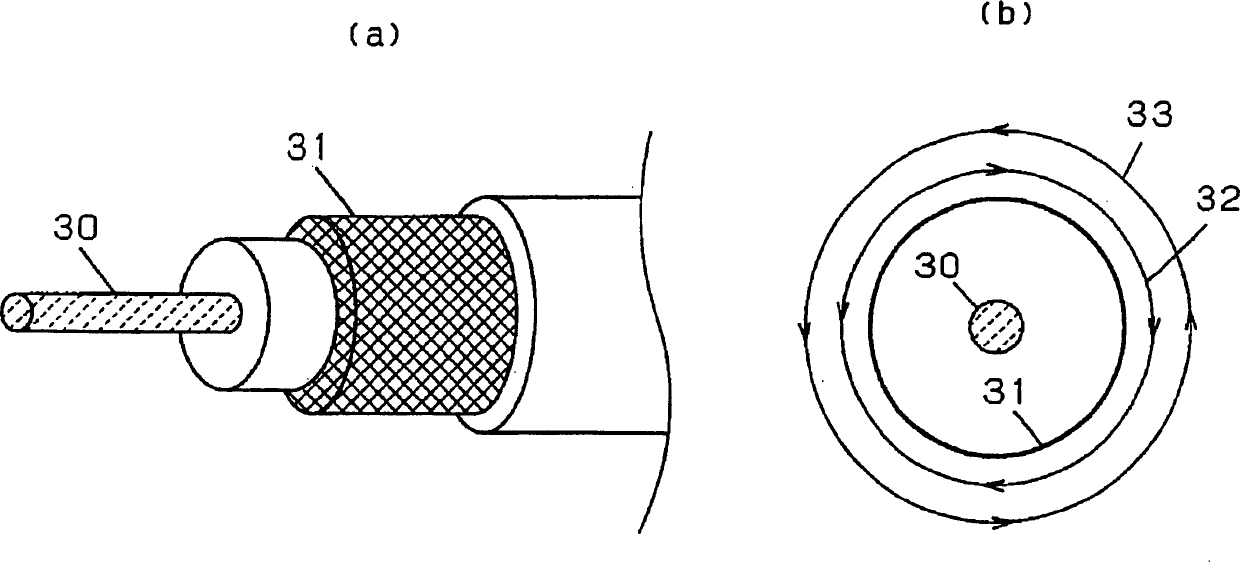
[0067] FIG. 2( a ) is a structural view of the shielded wire 29 , and the outer peripheral wire 31 wraps around the core wire 30 . FIG. 2( b ) is a magnetic field direction diagram of the shielded wire 29 . Because the current of the core wire 30 flows in the opposite direction to the current of the outer peripheral wire 31, the magnetic field 32 generated by the current of the core wire 30 and the magnetic field...
Embodiment approach 2
[0079] FIG. 6 shows a circuit diagram of an electric compressor drive unit. From the electric compressor driving device shown in FIG. 1, the current sensor 15, the voltage detection unit 16, and the current detection unit 17 are removed, and a current detection resistor 42, an integration resistor 43, an integration capacitor 44, and a sub relay are added. 48. The film capacitor 28, and the 12V power supply 22 is not connected.
[0080] The inverter control microcomputer 19 and the like using the 12V power supply 22 are powered by the switching power supply 12 . Also, the ground is set to be the same as that of the battery 1 . The communication circuit 20 and the air-conditioning control unit 21 communicate using a photocoupler while being electrically insulated. The divided voltages of the upper side voltage dividing resistor 13 and the lower side voltage dividing resistor 14 can be directly input to the microcomputer 19 for inverter control.
[0081] In addition, the curr...
Embodiment approach 3
[0093] FIG. 9 shows a circuit diagram of an electric compressor driving device. Different from the circuit diagram of the electric compressor driving device shown in FIG. 1 , the power lead line is made into one parallel line 34 .
[0094] FIG. 10 shows the configuration of parallel lines 34 in FIG. 9 .
[0095] The parallel wires 34 pass through a bendable electrically insulating resin 35 to keep the two conducting wires 36 parallel. It is not limited to this form, and it can also be realized by wrapping it with a tape, or passing two lead wires through a vinyl tube.
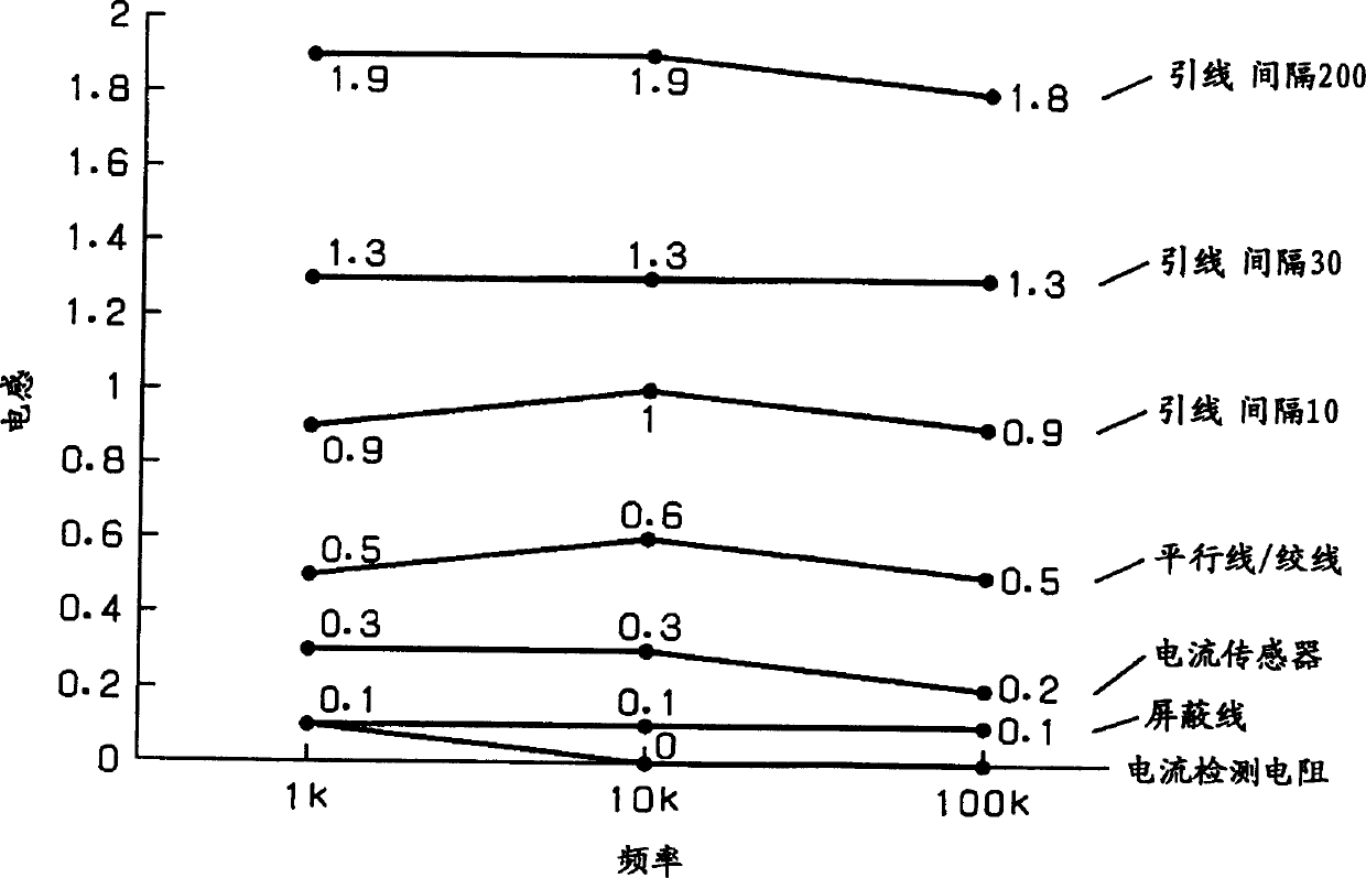
[0096]In the case of parallel wires as shown in FIG. 3, though not shielded wires, the inductance value is small. In addition, in the case of parallel wires, since the distance between the two conducting wires 36 is constant, the inductance value is constant, enabling a reliable design with a specific inductance value.
[0097] Since there is one parallel wire, it is easier to handle than two lead wires. In...
PUM
 Abstract
Description
Claims
Application Information
 - R&D
- Intellectual Property
- Life Sciences
- Materials
- Tech Scout
- Unparalleled Data Quality
- Higher Quality Content
- 60% Fewer Hallucinations
Browse by: Latest US Patents, China's latest patents, Technical Efficacy Thesaurus, Application Domain, Technology Topic, Popular Technical Reports.
© 2025 PatSnap. All rights reserved.Legal|Privacy policy|Modern Slavery Act Transparency Statement|Sitemap|About US| Contact US: help@patsnap.com