Output filter and power converter using output filter

An output filter and power converter technology, applied in output power conversion devices, control electromechanical transmission devices, irreversible DC power input conversion into AC power output and other directions, can solve the reduction of filter characteristics and the occurrence of filter cut-off frequency Changes, the inability to suppress the impulse voltage of the motor terminals, etc., to achieve the effects of suppressing the impulse voltage, suppressing the common mode voltage, and excellent high-frequency characteristics

Active Publication Date: 2013-02-13
YASKAWA DENKI KK
View PDF6 Cites 0 Cited by
  • Summary
  • Abstract
  • Description
  • Claims
  • Application Information

AI Technical Summary

Problems solved by technology

[0007]However, the common mode filter represented by Patent Document 1 and 2, and Non-Patent Document 1 has the problem of being unable to suppress the surge voltage on the motor terminal
Furthermore, the method of Non-Patent Document 2 has the problem that if the length of the motor cable is changed, the cutoff frequency of the filter changes, and it can only be used for a specific application.
In addition, there is a problem that the filter characteristics are generally degraded at high frequencies due to parasitic capacitance or wiring inductance scattered in various parts of the circuit, and damping resistors used in the shunt circuit part of the filter.
In this way, the conventional output filter has the following problems, it can only be used for a specific purpose, and the filtering characteristics cannot be fully exhibited when the frequency becomes high

Method used


Image

  • Output filter and power converter using output filter
  • Output filter and power converter using output filter
  • Output filter and power converter using output filter

Examples


Embodiment 1

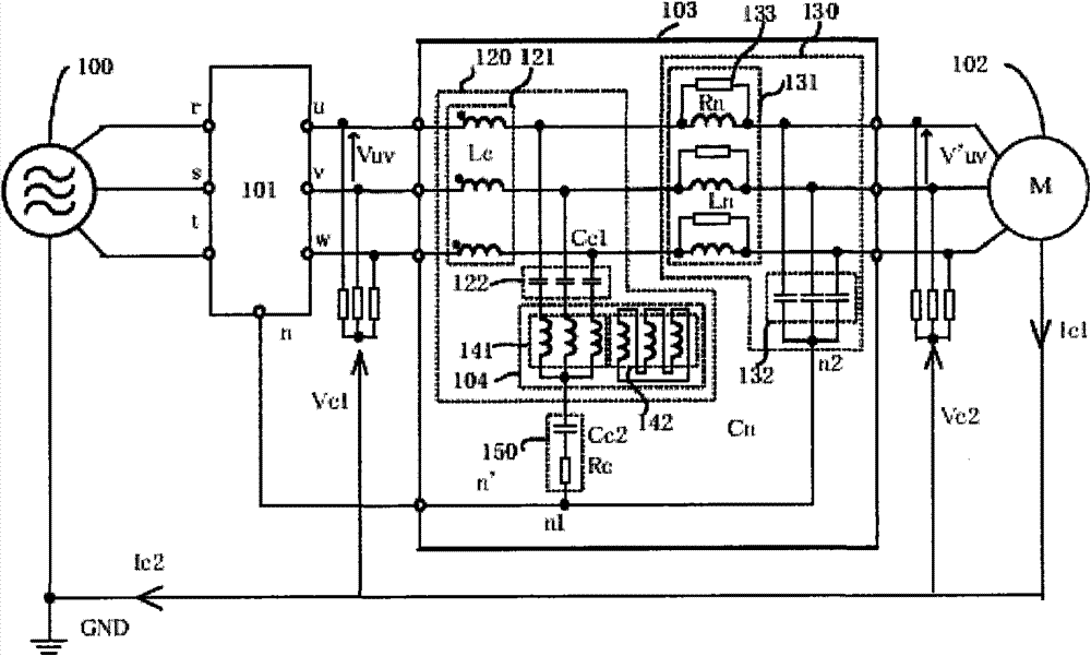
[0030] figure 1 It is a block diagram showing the configuration when the output filter of the present invention is applied to a motor drive system. In the figure, 100 is a power supply, 101 is a power converter, 102 is a motor, 103 is an output filter of the present invention, and 104 is a neutral point detection transformer. Furthermore, 120 is a polyphase common mode filter, 121 is a polyphase common mode choke coil Lc, 122 is a first polyphase capacitor Cc1, 130 is a polyphase normal mode filter, 131 is a polyphase normal mode choke coil Ln , 132 is the second polyphase capacitor Cn, 133 is the parallel resistor Rn, 141 is the primary coil of the neutral point detection transformer 104, 142 is the secondary coil of the neutral point detection transformer 104, and 150 is the series connection body of the capacitor resistor Cc2, Rc.

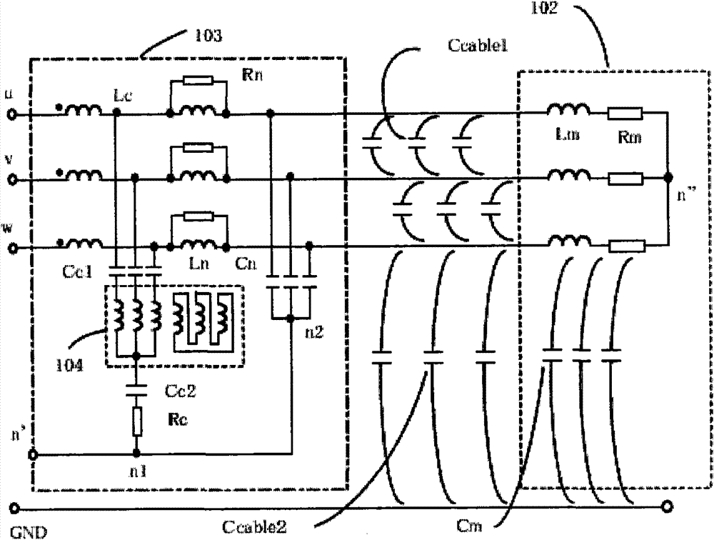
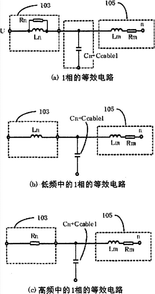
[0031] exist figure 2 Indicates the wiring diagram between the power conversion device and the motor, in image 3 In represents the equiva...

Embodiment 2

[0034] Figure 4 It is a block diagram showing the configuration of the second embodiment. Figure 4 (a) represents the case without an output filter, Figure 4 (b) represents the case of using the output side filter of the prior art, Figure 4 (c) shows a circuit diagram when the output-side filter of the present invention is used. and, Figure 5 means to use Figure 4 (b) is the common-mode equivalent circuit of the prior art output-side filter, and expresses the use of Figure 4 (c) Common mode equivalent circuit of the output side filter of the present invention. Such as Figure 4 As shown, since the output side filter of the present invention connects the return line n1 of the common mode filter and the neutral point n2 of the normal mode filter, so as Figure 5 As shown, the impedance of the shunt circuit part of the common mode filter becomes small. exist Figure 8 The middle represents the filter characteristics when using the conventional art and the output s...


PUM


Abstract

An output filter includes a polyphase common-mode filter having a polyphase common-mode choke connected to an output of a power converter at one end, a first polyphase capacitor connected to the other end of the polyphase common-mode choke at one end, and a neutral-point detecting transformer connected to the other end of the first polyphase capacitor at one end; a capacitor / resistor series-connected body connected to a frame ground of the power converter at one end and connected to the other end of the neutral-point detecting transformer at the other end; and a polyphase normal-mode filter having a polyphase normal-mode choke connected to the other end of the polyphase common-mode choke at one end, and a second polyphase capacitor connected to the other end of the polyphase normal-mode choke at one end and having the other ends connected together and further connected to the one end of the capacitor / resistor series-connected body.

Description

technical field [0001] The invention relates to an output filter and a power conversion device using the filter, which can reduce high-frequency interference generated by switching operations of the power conversion device. Background technique [0002] The prior art of the output filter will be described. Examples of problems on the output side of the power conversion device include high-frequency leakage current, surge voltage on motor terminals, and the like. Conventionally, in order to solve the above-mentioned problems, an output filter is added to the output side of the power conversion device. For example, Patent Documents 1 and 2 and Non-Patent Documents 1 and 2 disclose output filters of conventional power conversion devices. Patent Documents 1 and 2, and Non-Patent Document 1 are common-mode filters for suppressing common-mode voltages. Non-Patent Document 2 is composed of a normal-mode filter for suppressing a surge voltage on a motor terminal and a common-mode...

Claims


Application Information

Patent Timeline
Patent Type & Authority Patents(China)
IPC IPC(8): H02M1/12H02M1/44H02M7/48H02P21/05H02P23/04H02P27/06H03H7/09
CPCH02M1/126H03H7/1758H03H1/0007H03H7/1725H03H7/427H03H7/09H02M1/123
Inventor 樋口刚山田健二
Owner YASKAWA DENKI KK
Why Eureka
Try Eureka