Intermittent drip irrigation belt

A drip irrigation belt and tubular technology, which is applied in the field of intermittent drip irrigation belt, can solve the problems of easy blockage of the outlet flow channel, increased energy consumption and cost, unfavorable drip irrigation promotion, etc., and achieves less consumables, low production cost, and low precision requirements Effect

Inactive Publication Date: 2004-03-31
覃永标
View PDF0 Cites 5 Cited by
  • Summary
  • Abstract
  • Description
  • Claims
  • Application Information

AI Technical Summary

Problems solved by technology

In order to dissipate energy, the water outlet channel of the dripper is generally made very small, which makes the water outlet channel of the dripper easy to be blocked
Dripper clogging can be solved by filtering and chemically treating the irrigation water, but energy consumption and costs also increase
Existing drippers discharge water in the way of dissipating energy in the outlet channel, and their working head is relatively high, generally 5m to 10m. There are very few water sources that can provide such a high pressure head, so the drip irrigation system generally needs to be equipped with pressurized equipment, which is Increased the cost of drip irrigation, which is not conducive to the promotion of drip irrigation

Method used


Image

  • Intermittent drip irrigation belt
  • Intermittent drip irrigation belt
  • Intermittent drip irrigation belt

Examples


Embodiment 1

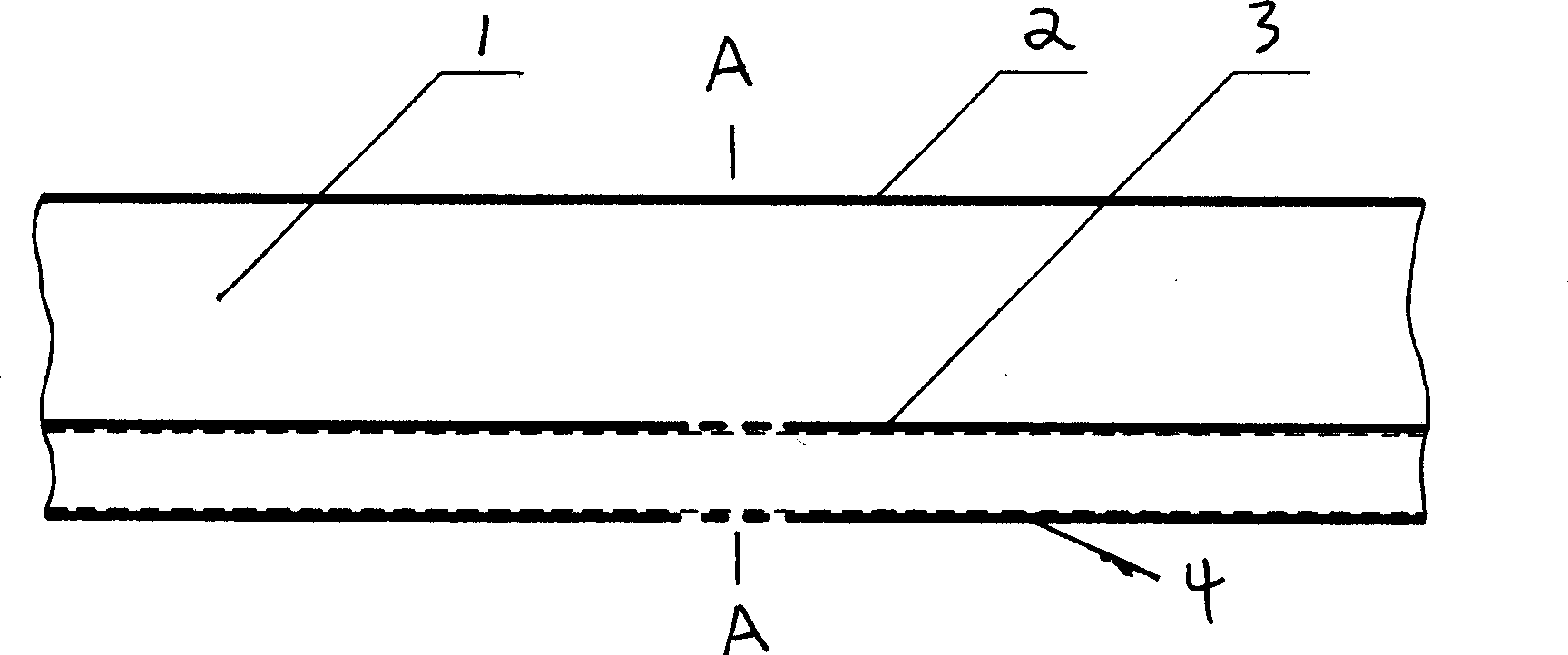
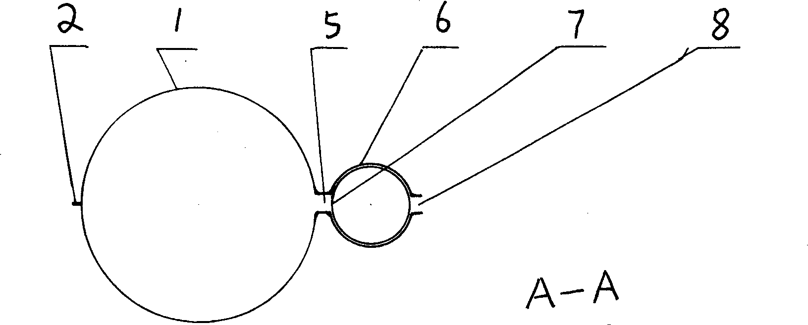
[0015] In Embodiment 1, the main pipe 1 is connected to the rubber tube valve, and the rubber tube valve is composed of a rubber tube valve core 7 and a valve sleeve, and the valve sleeve is composed of a thin film tube valve seat 6 and several pairs of water inlet and outlet. The water inlet 5, the film tube valve seat 6, the rubber tube spool 7 and the water outlet 8 form a valve unit, and several valve units form the rubber tube valve. The main pipe 1 and the valve sleeve of embodiment 1 can be welded together with two plastic films, figure 1 The thick solid lines 2, 3, and 4 are all welding lines, and the dotted line on the same line as the welding line is where the water inlet or water outlet is located. The film at the dotted line and its left and right sides can be properly stretched during the production process to ensure Widen the inlet and outlet. Embodiment 1 is a gravity water separation type intermittent drip irrigation belt, which must be placed on the ground or...

Embodiment 2

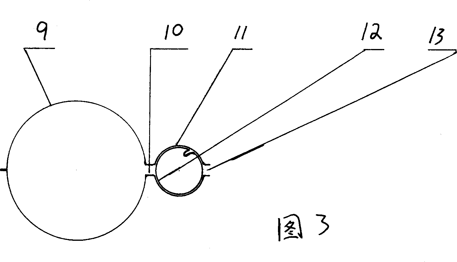
[0016] The difference between embodiment 2 and embodiment 1 lies in the valve core, the valve core of embodiment 2 is a film tube, and the valve core of embodiment 1 is a rubber tube. In embodiment 2, the main pipe 9 is connected to the membrane tube valve, and the membrane tube valve is composed of a membrane tube valve core 12 and a valve sleeve, and the valve sleeve is composed of a membrane tube valve seat 11 and several pairs of water inlet and outlet. Water inlet 10, film tube valve seat 11, film tube spool 12 and water outlet 13 constitute a valve unit, and several valve units just constitute a film tube valve. Embodiment 2 belongs to gravity water separation type intermittent drip irrigation belt, and its working principle is the same as that of embodiment 1.

Embodiment 3

[0017] In Embodiment 3, the main pipe 14 is connected to the diaphragm pipe valve, and the diaphragm pipe valve is composed of a diaphragm valve core 17 and a valve sleeve, and the valve sleeve is composed of a film tube and several pairs of water inlets and outlets. The lower wall 19 (valve seat) and the upper wall 15 constitute. Water inlet 16, upper wall 15, diaphragm spool 17, lower wall 19 and water outlet 18 constitute a valve unit, and several valve units constitute a diaphragm pipe valve. Embodiment 3 belongs to gravity water separation type intermittent drip irrigation belt, and its working principle is the same as that of embodiment 1.


PUM


Abstract

It relates to an intermittent drip-irrigating strap with a variety of structures, which could realize the circulation of the water diversion and release. There are three kinds of water diversion modes in the invention, gravitation water diversion, water storage Vesicae Cubage water diversion and main pipe segment water diversion. An intermittent drip irrigating strap with gravitation water diversion is placed on the wavy ground or material, the water outlet is at the bottom, the delivery pipe is controlled by a pipe-like valve. For an intermittent drip-irrigating strap with water storage Vesicae Cubage water diversion, the water intake pipe and the water delivery pipe are controlled by pipe-like valves. For an intermittent drip-irrigating strap with main pipe segment water diversion, the water delivery pipe in each section is controlled by pipe-like valves. The pipe-like valve comprises a valve jacket and a valve core in the jacket. The valve jacket is a plastic film pipe having a pair of water inlet and water outlet at intervals. The valve core is an active sealing member, including three kinds, rubber, plastic film and plastic membrane.

Description

technical field [0001] The invention relates to a drip irrigation drip device, in particular to a type of intermittent drip irrigation belt. Background technique [0002] At present, drip irrigation emitters discharge water in the way of energy dissipation in the outlet channel, so as to achieve the purpose of slow water discharge and uniform irrigation. It can be said that energy dissipation is the essential feature of current drippers. In order to dissipate energy, the water outlet channel of the dripper is generally made very small, which makes the water outlet channel of the dripper easily blocked. The problem of clogged drippers can be solved by filtering and chemically treating the irrigation water, but the energy consumption and cost will also increase. Existing drippers discharge water in the way of dissipating energy in the outlet channel, and their working head is relatively high, generally 5m to 10m. There are very few water sources that can provide such a high p...

Claims


Application Information

Patent Timeline
Patent Type & Authority Applications(China)
IPC IPC(8): A01G25/02
CPCA01G25/02Y02A40/22
Inventor 覃永标
Owner 覃永标
Why Eureka
Try Eureka