
Station-charging trollybus system

A trolley bus and rechargeable technology, which is applied to electric vehicles, current collectors, vehicle components, etc., can solve the problems that cannot be achieved, do not involve pantograph double-wire power receiving structure, automatic line-to-line network connection method, and application range limitations. Achieve the effect of short length, improve flexibility and mobility, and get rid of the constraints of the wire network

Inactive Publication Date: 2004-04-07
SHANGHAI JIAO TONG UNIV
View PDF1 Cites 28 Cited by
  • Summary
  • Abstract
  • Description
  • Claims
  • Application Information

AI Technical Summary

Problems solved by technology

"Although this utility model can be used for the transformation of trolleybuses and increase the flexibility of the power supply of existing trolleybuses, the power supply of the transmission motor of the new trolleybus is automatically converted, and the grid power supply / battery power supply is respectively connected to the transmission motor. It shows that it still cannot run completely away from the power grid; although the utility model mentions that the pantograph uses motors and ropes to automatically go on and off the power grid, it does not involve the double-wire power receiving structure of the pantograph and its safe and reliable automatic alignment. This is the key to whether most of the overhead power supply catenary network of trolleybuses can be canceled and trolleybuses can run off-grid. Since the requirements for basically dismantling the current overhead power supply catenary network cannot be met, the application of this type of technology very limited range

Method used


Image

  • Station-charging trollybus system
  • Station-charging trollybus system
  • Station-charging trollybus system

Examples


Embodiment Construction

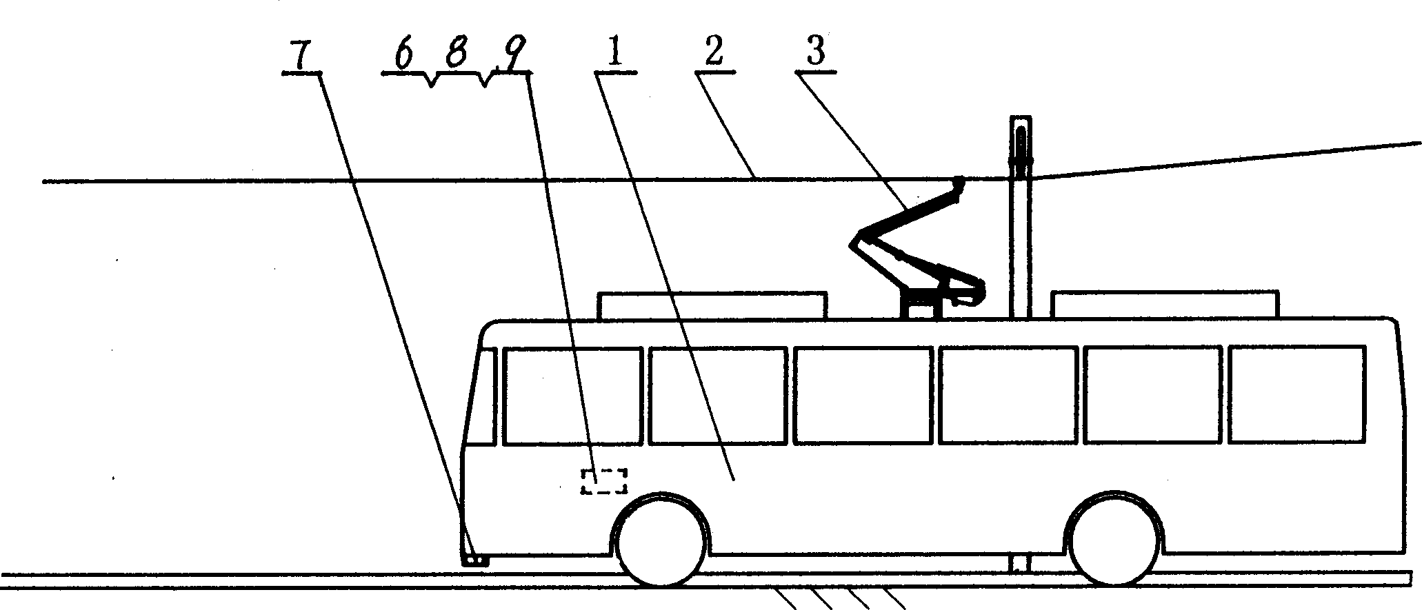
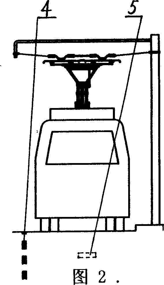
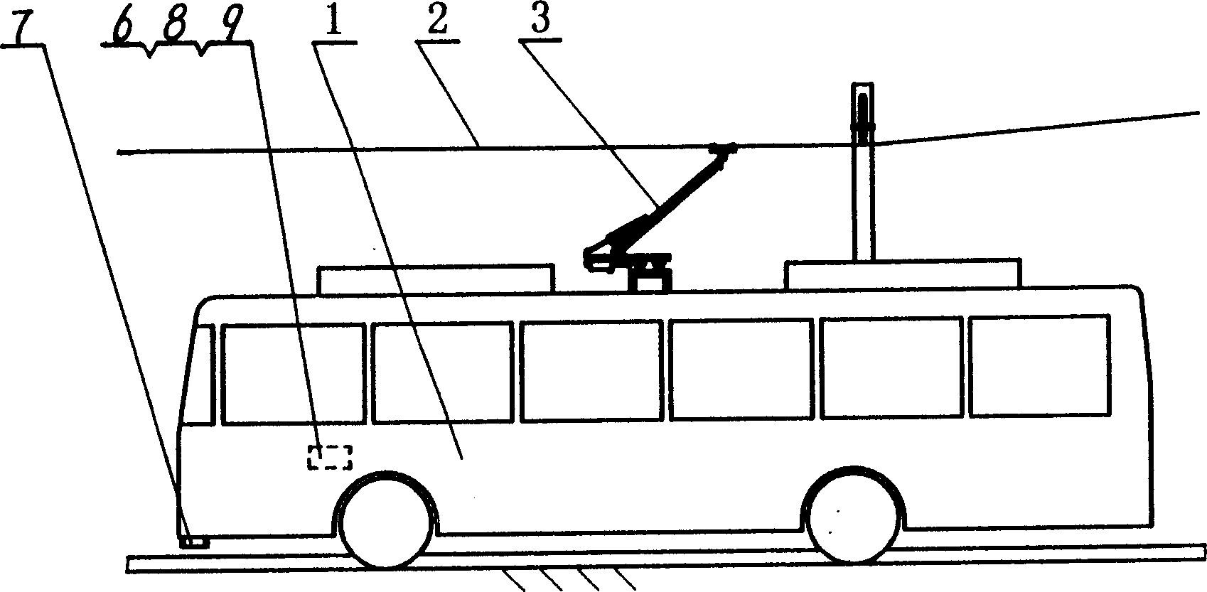
[0013] Such as figure 1 Figure 2 and Figure 3 As shown, the present invention includes: trolley bus 1, trolley bus catenary 2, double-wire power receiving type pantograph 3, ground road sign 4 in the station area, sensing source 5, power receiving switch device 6, and its connection mode is: double The line-receiving pantograph 3 is installed on the roof of the trolley bus 1 as the charging and receiving device of the trolley bus 1. The double-wire receiving pantograph 3 is in contact with the catenary 2 of the trolley bus in the charging station area, and receives power. The switch device 6 is arranged on the trolleybus 1, and the sensing source 5 is a passive metal part pre-buried on the ground of the entrance of the station within the boundary line of the ground road sign 4 in the station area, and the upper part of the corresponding position is the network entry end of the trolleybus catenary 2 Gradient sloping suspension section outside.

[0014] The trolleybus catenar...


PUM


Abstract

The station-charging trolleybus system for city public traffic includes trolleybus, contact network, double-wire current collecting pantograph, station ground road mark, sensing source and current collecting switch device. The connection mode includes setting the double-wire current collecting pantograph in the top of the trolleybus, contacting the double-wire current collecting pantograph to the contact network in the charging station, setting the current collecting switch device inside the trolleybus, and embedding passive metal parts on the ground of station entrance as the sensing source corresponding to the suspended section of the network access. The present invention has reasonable system constitution, network-free running of the trolleybus, low cost of the trolleybus and attached equipment, safe and reliable operation and simple implementation.

Description

technical field [0001] The invention relates to a trolleybus system, in particular to a system of charging type trolleybus in a station area as an urban public transportation tool, which belongs to the field of urban public transportation. Background technique [0002] At present, the trolley bus used for urban public transportation has the characteristics of low noise, no emission pollution, quick start and fast uphill, but due to the existence of overhead power supply contact wire network, roof collector pole and collector slipper, it makes the The tram cannot overtake the tram, and if the collector slipper jumps off the catenary wire during driving, it will easily lead to traffic congestion and affect the landscape above the city street; the trolleybus with large-capacity battery energy storage can not completely rely on the overhead power supply catenary network to run , but due to limited energy storage, it still needs to intermittently obtain electric energy from the c...

Claims


Application Information

Patent Timeline
IPC IPC(8): B60L5/20
Inventor 程晓鸣陈杰林忠钦殷跃红李忠学
Owner SHANGHAI JIAO TONG UNIV
Learn More