Heat cooking apparatus and self-cleaning material and producing method thereof

A technology of cooking device and functional material, applied in the field of thermal cooking device

Inactive Publication Date: 2004-04-07
PANASONIC CORP
View PDF0 Cites 24 Cited by
  • Summary
  • Abstract
  • Description
  • Claims
  • Application Information

AI Technical Summary

Problems solved by technology

[0011] In the above-mentioned glazing treatment and other treatments, such as ceramic coating, since the thermal insulating resin i

Method used


Image

  • Heat cooking apparatus and self-cleaning material and producing method thereof
  • Heat cooking apparatus and self-cleaning material and producing method thereof
  • Heat cooking apparatus and self-cleaning material and producing method thereof

Examples


Embodiment Construction

[0062] Hereinafter, a preferred embodiment of the thermal cooking device according to the present invention will be described in detail with reference to the accompanying drawings.

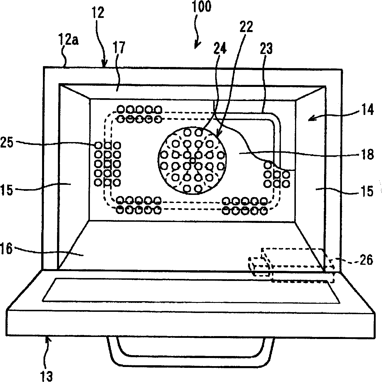
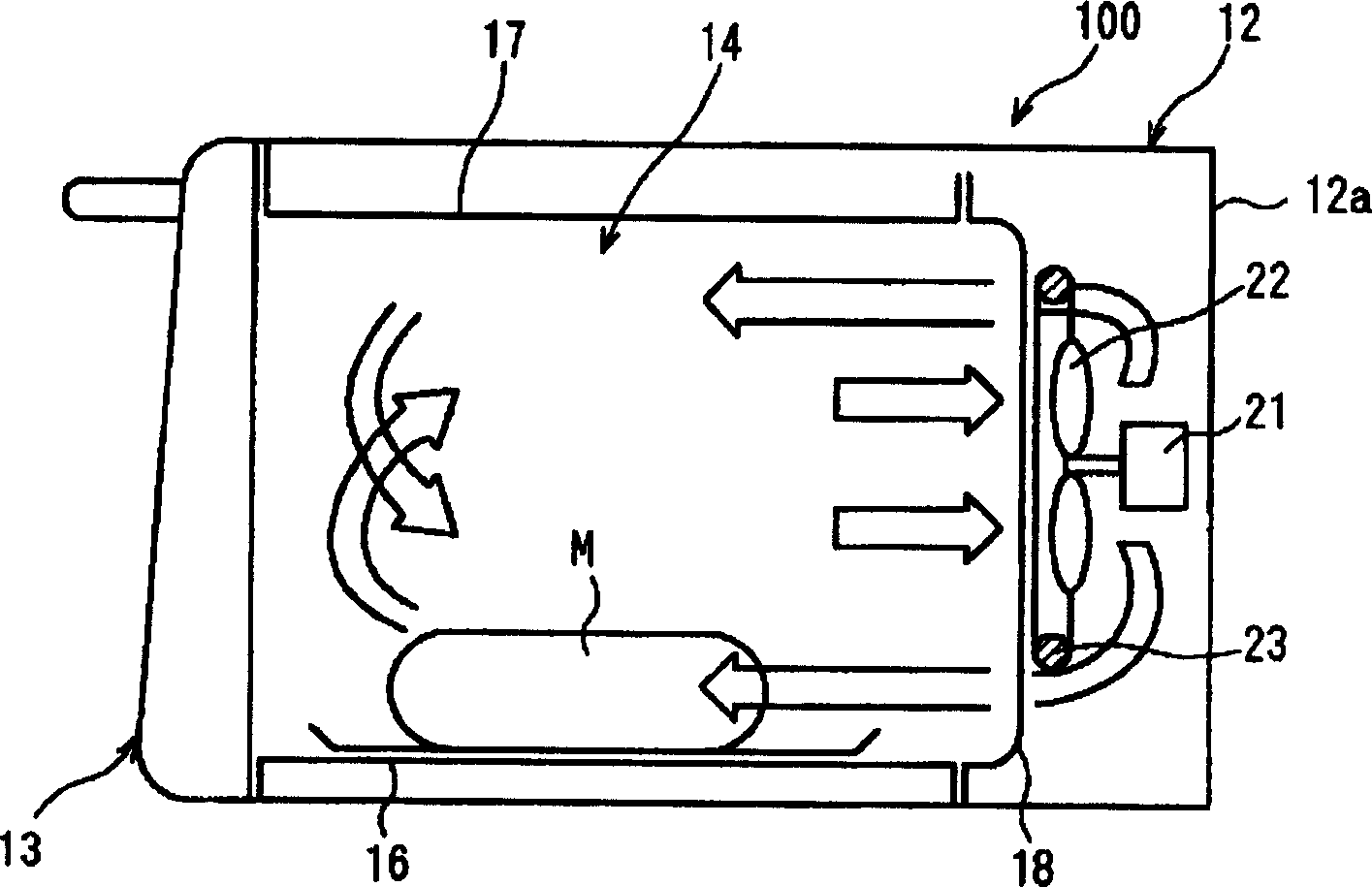
[0063] figure 1 is a front view showing the outline structure of the thermal cooking device of the present invention, figure 2 is a schematic cross-sectional view of the thermal cooking device of the present invention.

[0064] Such as figure 1 with figure 2 As shown in , the thermal cooking device 100 of this embodiment has a cooking device main body 12 and an opening and closing door arranged on the front side of the cooking device main body 12 . In the main casing 12a that shapes the cooking device main body 12, a heating chamber in which an object M to be heated can be placed is formed, and is designed so that the space in the heating chamber 14 can be opened and closed by an opening and closing door 13.

[0065] The top, bottom, left and right sides of the heating chamber 14 formed in...


PUM


Abstract

A convection heater (23) is disposed along a back surface of a rear face plate (18) which is comprised of a stainless steel plate that forms a heating chamber (14). On a back side of the rear face plate (18), disposed is a circulation fan (22) by which, air in the heating chamber (14) is sucked from air intake use through-holes into the back side, and after it is heated by the convection heater (23), it is returned from air blowing use through-holes to the heating chamber. On a surface of an inner side of the heating chamber (14) of the rear face plate (18), a self-cleaning layer is formed by dissolving a self-cleaning material which oxide-decomposes and removes accreted dirt at high temperature into a porcelain enamel glaze and by applying and bake-sticking.

Description

technical field [0001] The present invention relates to a thermal cooking device such as an oven / oven, in particular to a thermal cooking device that behaves hygienically and environmentally. The invention also relates to a self-cleaning material which uses stainless steel as a substrate and completes the self-cleaning function at high temperature and a production method thereof. Background technique [0002] In the thermal cooking device, the inner wall surface of the thermal cooking device becomes dirty due to liquid etc. splashed from food and condiments through cooking, and the liquid etc. adhering to the wall surface heated at high temperature is transformed into varnish, so it is strongly desired to remove such prevents this kind of dirt and keeps the heating chamber clean at all times. [0003] For this reason, in order to remove the attached dirt, a coating agent containing a self-cleaning material (hereinafter referred to as SC material) has been arranged in the he...

Claims


Application Information

Patent Timeline
IPC IPC(8): F24C14/00F24C15/00F24C15/32
CPCF24C14/00F24C15/005F24C15/325
Inventor 今井修二松田正人
Owner PANASONIC CORP
Why Eureka
Try Eureka