Making process of image-transmitting soft fiber tow

A manufacturing method and image transmission beam technology, which is applied in the direction of optical fiber bundles, can solve the problems of difficult manufacturing and easy broken wires, and achieve the effects of reducing the broken wire rate, improving resolution, and increasing light transmittance

Inactive Publication Date: 2004-04-07
崔开源
View PDF0 Cites 0 Cited by
  • Summary
  • Abstract
  • Description
  • Claims
  • Application Information

AI Technical Summary

Problems solved by technology

The acid-soluble method is to arrange the single fiber material into a composite fiber rod and then draw it into a filament, and then corrode the soluble glass added on the surface of the single fiber material with acid. It is very difficult to manufacture image bundles with a fiber cross-sectional diameter of less than 8um by acid-dissolving method, and it is easy to cause broken filaments

Method used


Image

  • Making process of image-transmitting soft fiber tow
  • Making process of image-transmitting soft fiber tow
  • Making process of image-transmitting soft fiber tow

Examples


Embodiment 1

[0018] In this embodiment, 271 (the specific number should be selected according to the cross-sectional size and resolution of the image beam, but at least 90) whose outer surface is 0.8mm in diameter is soluble glass, the middle is low refractive index glass, and the inner core is high Refractive index glass, a single fiber material with a length of 500mm is arranged into a composite fiber rod with a regular hexagonal cross-section, which is bound and bound; the above composite fiber rod is drawn into a composite fiber filament with a diameter of 0.8mm by a wire drawing machine; the above drawn The formed composite fiber filaments of the same specification are arranged into a composite fiber rod with a diameter of 25 mm; the two ends of the composite fiber rod are partially fused at high temperature to form a cone; the two ends of the composite fiber rod are protected with acid-resistant rubber, and the middle The unfused composite fiber rods were placed in 10% HNO by weight ...

Embodiment 2

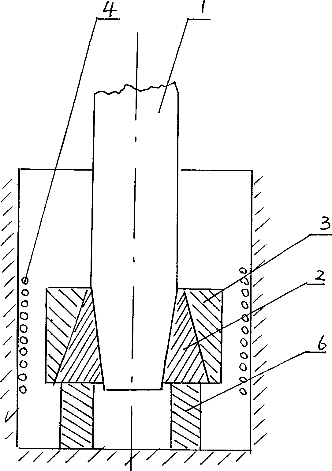
[0020] The method of locally fusing the two ends of the composite fiber rod at high temperature to form a cone as described in Example 1 can use figure 1 As shown, the end of the composite fiber rod 1 is placed in the heating furnace 4 , the end of the composite fiber rod 1 is covered with a briquetting block 2 and a pressure ring 3 , and a pad 6 is provided under the briquetting block 2 . During processing, the end of the composite fiber rod 1 and the briquetting block 2 are locally heated, and then the pressure ring 3 tightens the briquetting block 2 placed on the pad 6 by adding force, so that the end of the composite fiber rod 1 Form a cone, then cool down slowly to relieve stress.

Embodiment 3

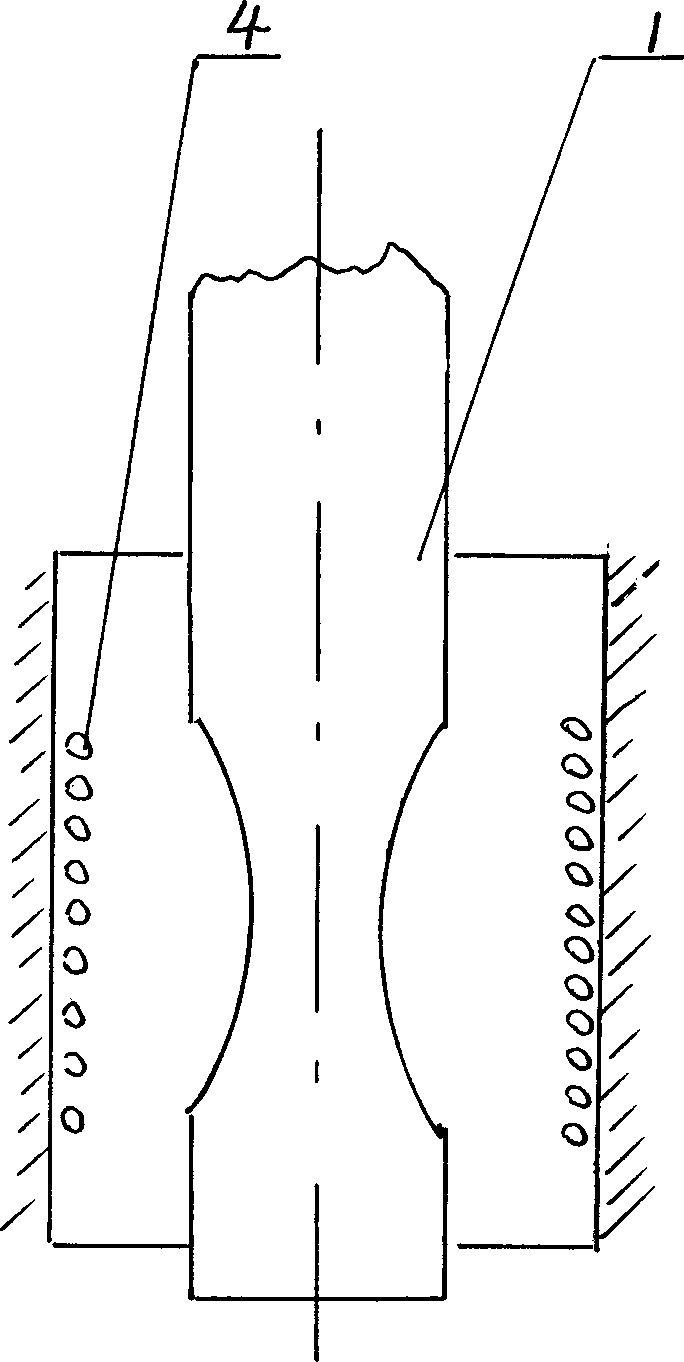
[0022] The method of locally fusing the two ends of the composite fiber rod at high temperature to form a cone as described in Example 1 can use figure 2 As shown, the end of the composite fiber rod 1 passes through the center of the hearth of the heating furnace 4 to start heating. When the temperature is higher than the softening temperature of the fiber (about 20-50°C), the fiber filament begins to soften, and the end of the composite fiber rod Under the action of gravity, the end of the composite fiber rod in the high temperature section is elongated to form a cone, and then the temperature is slowly lowered to eliminate the stress.


PUM

PropertyMeasurementUnit
diameteraaaaaaaaaa
diameteraaaaaaaaaa
lengthaaaaaaaaaa

Abstract

The making process of image-transmitting soft fiber tow includes acid dissolving to arrange single fiber material into composite fiber rod, drawing into filament, protecting two ends with acid resisting rubber, acid eroding un-fused soluble glass in the surface of the composite fiber filament in the middle part, adding middle outer protecting casing and adding protecting metal caps in two ends. It features the local high temperature fusion of the two ends of composite fiber rod to form cones before acid erosion. The present invention has the advantages of maintaining the merits of acid dissolving method, capacity of making large cross section area image transmitting fiber tow, greatly raised resolution and light transmittance and less filament breakdown. The method of the present invention may be used also in making light-transmitting fiber tow.

Description

Technical field: [0001] The invention relates to a method for manufacturing a soft fiber image-transmitting bundle. Background technique: [0002] Soft fiber image beams are widely used in military and industrial and medical equipment detection equipment for scene image transmission. Due to the wide range of diameter requirements for soft fiber image beams (1mm to 30mm), high resolution (above 801P / mm) , the center distance of a single fiber filament is less than 10um, and the production process requires high requirements. [0003] At present, the commonly used methods are wire winding method, lamination method and acid solution method. Since the wire winding method and the lamination method are directly processed by very thin single fibers, the strength of a single fiber with a diameter of less than 15um is very poor, and it is not easy to use the wire winding method, and the wire winding method is very easy to form cumulative errors. It is subject to certain restrictions...

Claims


Application Information

Patent Timeline
Patent Type & Authority Applications(China)
IPC IPC(8): G02B6/04
Inventor 崔开源
Owner 崔开源
Why Eureka
Try Eureka