Vibrative micro electric field sensor

An electric field sensor, sensor technology, applied in the sensor field, can solve the problems of limitation, narrow measurement range and high cost

Inactive Publication Date: 2004-04-28
INST OF ELECTRONICS CHINESE ACAD OF SCI
View PDF0 Cites 24 Cited by
  • Summary
  • Abstract
  • Description
  • Claims
  • Application Information

AI Technical Summary

Problems solved by technology

The production technology of the charge-inductive electric field sensor is relatively mature, and the measuring range is large, but due to its large size, the applicati

Method used


Image

  • Vibrative micro electric field sensor
  • Vibrative micro electric field sensor
  • Vibrative micro electric field sensor

Examples


Embodiment Construction

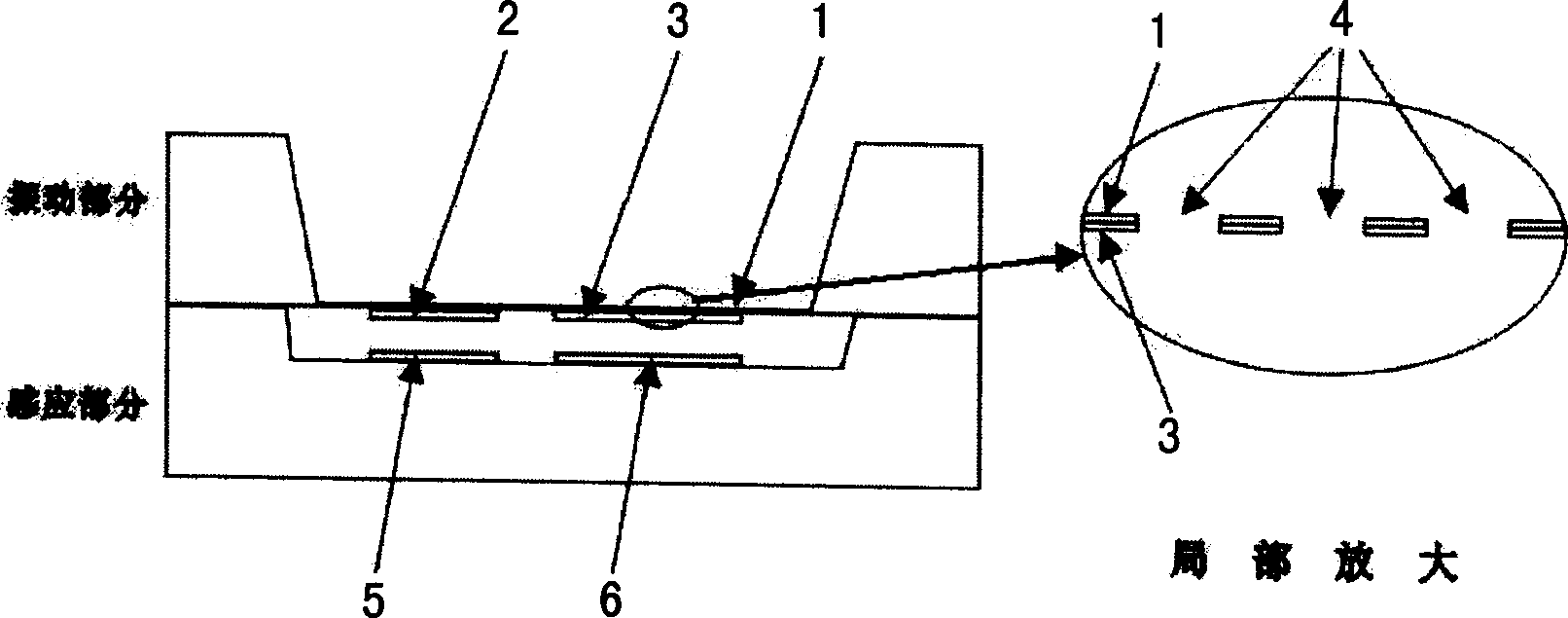
[0009] The structure of the vibrating miniature electric field sensor is as follows: figure 1 As shown, it is composed of vibration and induction parts, which are respectively prepared on the basis of single crystal silicon, and finally bonded as a whole.

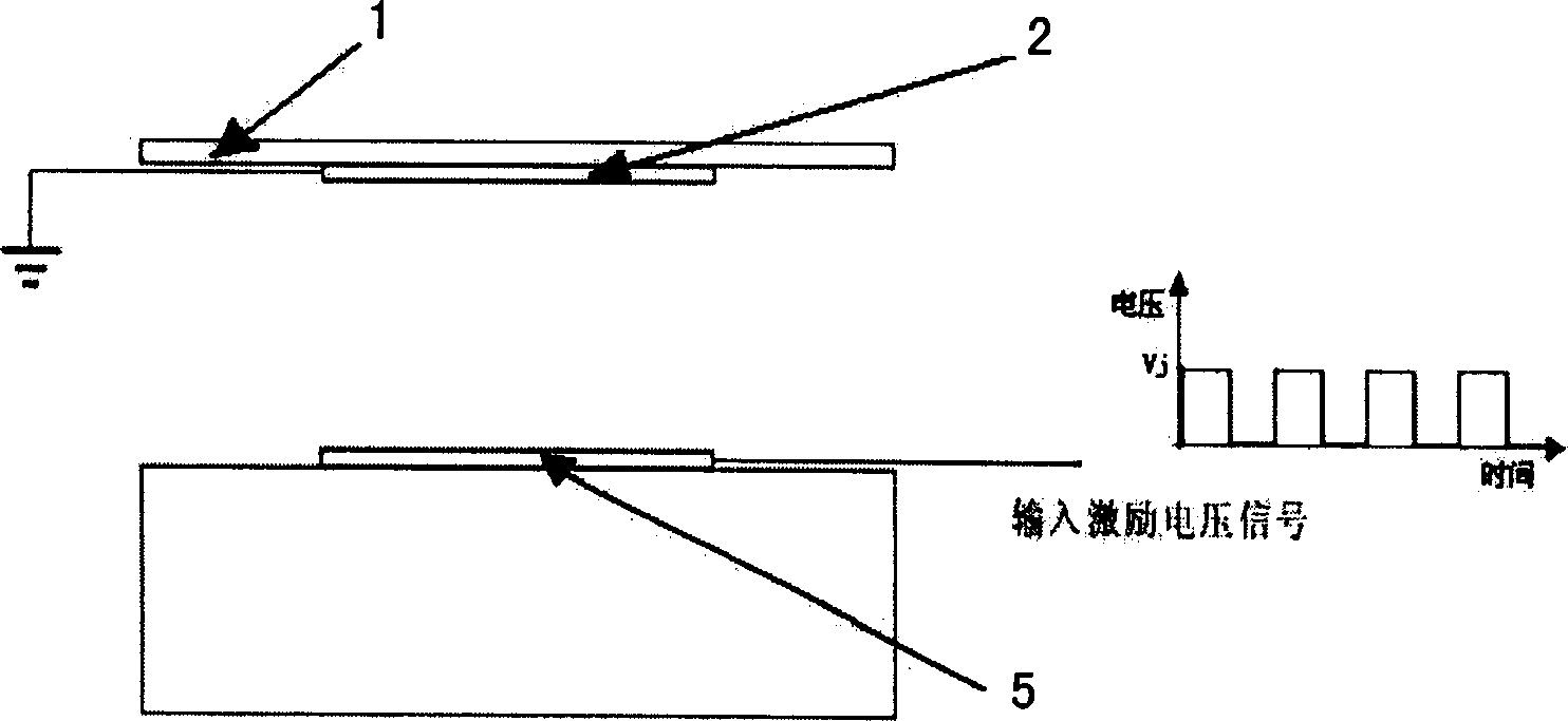
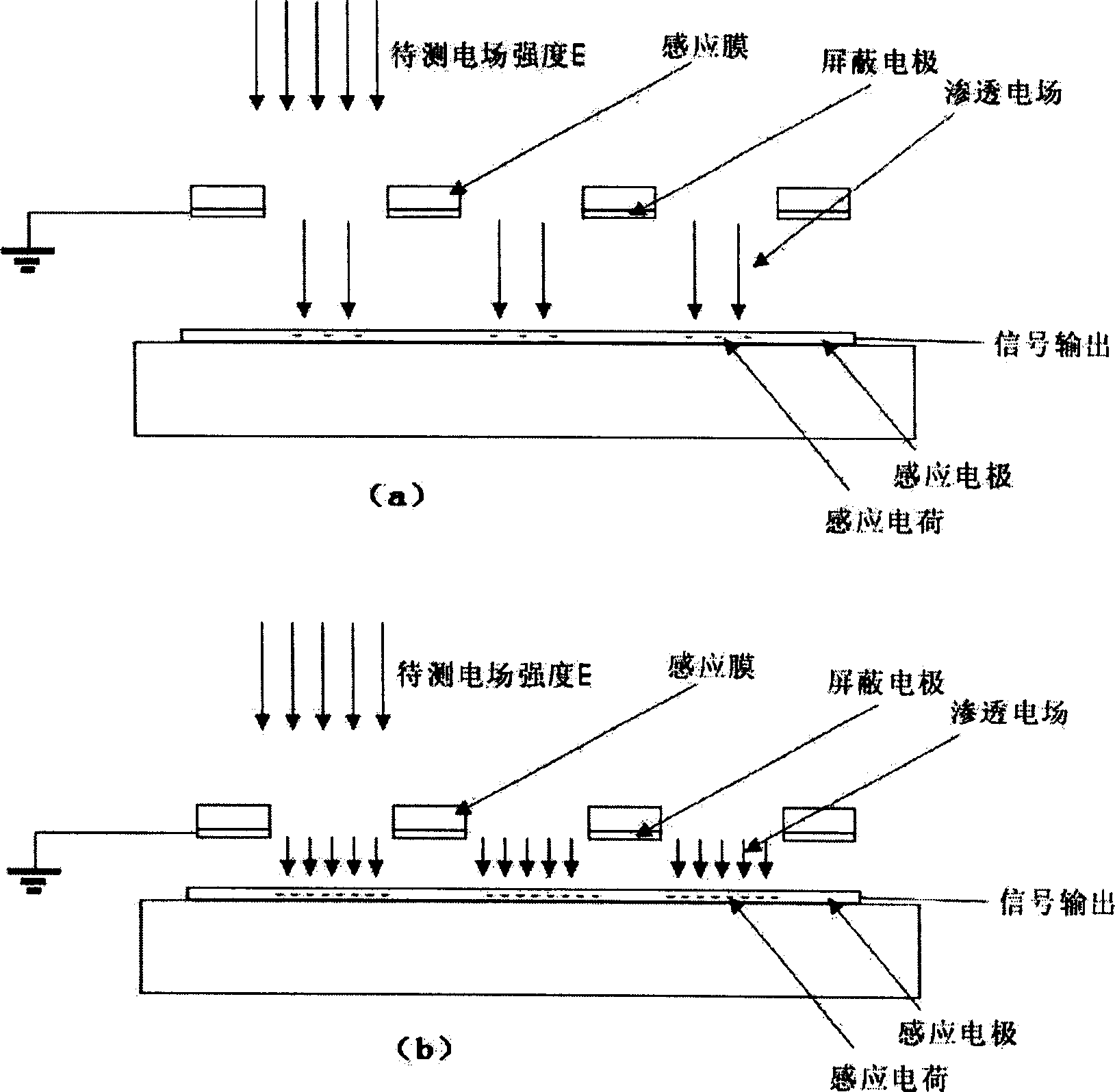
[0010] Vibration part: a silicon nitride film is grown on one side of the silicon wafer, and the silicon nitride film is formed by deep etching on the other side, which is the vibrating film 1 . Electrodes are prepared on the vibrating membrane 1, including the excitation electrode cathode 2 and the shielding electrode 3, both of which are insulated from each other, and the shielding electrode 3 is grounded. There is a gate hole 4 on the shielding electrode 3, and the shape of the hole 4 is a square hole, a round hole or other shapes. The number of grid holes is made as required, but at least one. The gate hole 4 should be as small as possible under the process conditions, for example, the area of ​​the gate hole is less ...


PUM

PropertyMeasurementUnit
Thicknessaaaaaaaaaa

Abstract

The vibration type micro electric field sensor includes vibration part and induction part, the vibration part is vibration film, the first excitation electrode and shielding electrode on the vibration film, and the induction part has the second excitation electrode and inducing electrode. The micro electric field sensor prepared based on the micro machining technology has small volume and low cost and is easy to mass produce.

Description

technical field [0001] The invention relates to a sensor, in particular to a vibrating miniature electric field sensor. Background technique [0002] Atmospheric electric field is a characteristic parameter across many disciplines. Many natural phenomena, such as: lightning, earthquakes, solar activities, etc., can cause corresponding changes in the atmospheric electric field. Some human activities, such as: environmental pollution, high-voltage power transmission, etc. will also change the atmospheric electric field in the near-earth range. At the same time, the atmospheric electric field will also have a certain impact on human production and life. The launch of spacecraft and artificial rainfall must fully take into account the conditions of the atmospheric electric field. Excessive electric fields may also cause delicate electronic equipment to fail, or even damage electronic equipment. Therefore, with the help of electric field sensors, it is necessary to effectivel...

Claims


Application Information

Patent Timeline
IPC IPC(8): G01R29/00
Inventor 夏善红裴强白强龚超
Owner INST OF ELECTRONICS CHINESE ACAD OF SCI
Why Eureka
Try Eureka