Digital lock phase ring for producing multiple frequency point clock signal using one time delay chain

A technology of digital phase-locked loop and clock signal, which is applied to the automatic control of power and electrical components, etc., which can solve the problems of reducing clock precision and increasing the occupied area, and achieve the effect of improving precision and saving chip area

Inactive Publication Date: 2004-05-05
PERICOM TECH (SHANGHAI) CO LTD
View PDF3 Cites 18 Cited by
  • Summary
  • Abstract
  • Description
  • Claims
  • Application Information

AI Technical Summary

Problems solved by technology

[0006] Since two identical delay chains are required here, there are always differences between the two delay chains in the actual circuit. This mismatch will inevitably reduce the accuracy of the generated clock; Eac

Method used


Image

  • Digital lock phase ring for producing multiple frequency point clock signal using one time delay chain
  • Digital lock phase ring for producing multiple frequency point clock signal using one time delay chain
  • Digital lock phase ring for producing multiple frequency point clock signal using one time delay chain

Examples


Embodiment Construction

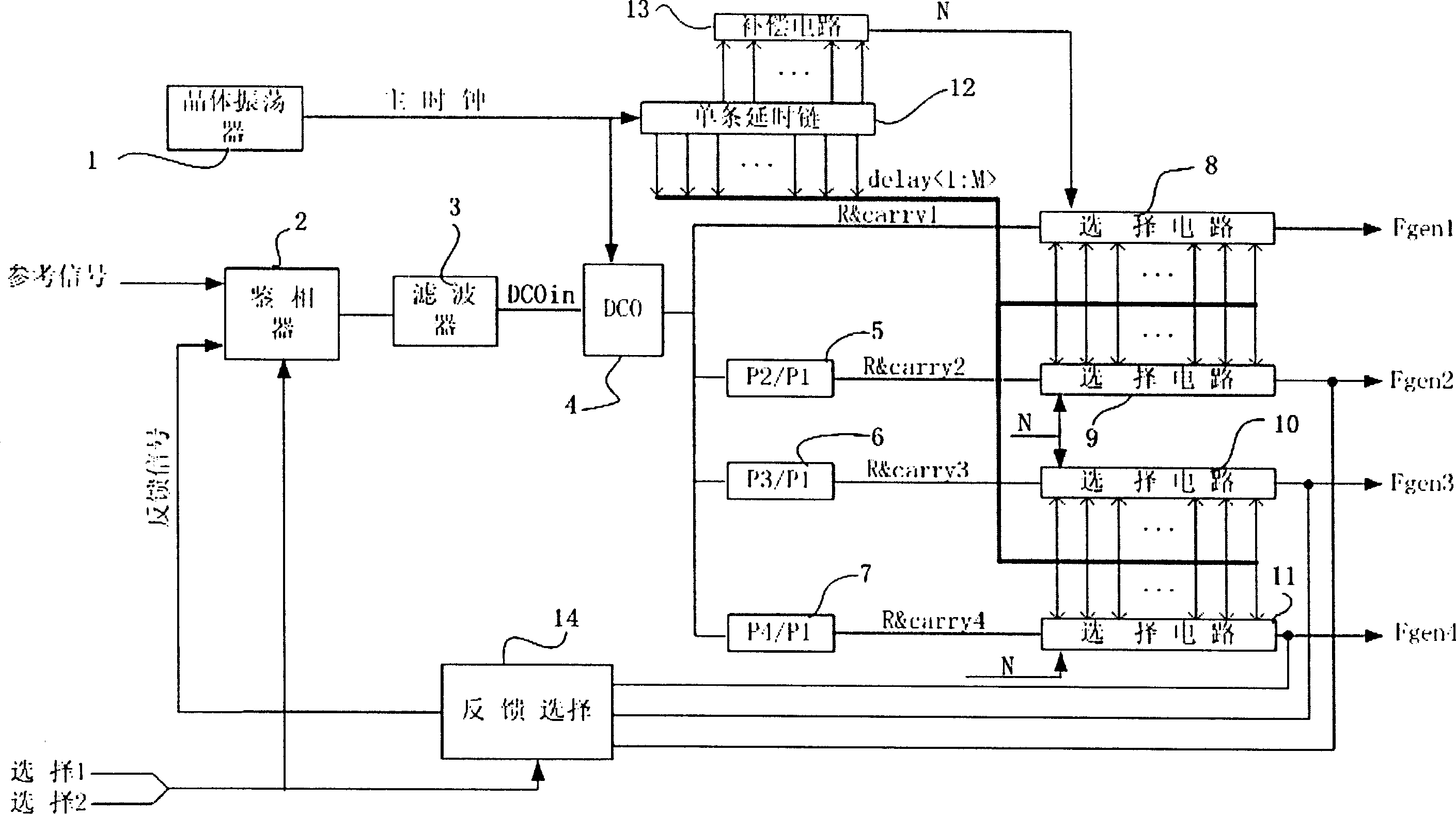
[0024] A digital phase-locked loop that uses a delay chain to generate multiple frequency point clock signals. The digital phase-locked loop can use at least one input signal as a reference to attenuate the jitter of the input signal to generate one or more relatively stable clock signals. , which includes: a) phase detection filter circuit, which compares the difference between the output clock and the reference signal, and filters out high-frequency components; b) digitally controlled oscillator (DCO for short); c) a crystal oscillator that provides the main clock; d) A delay chain with taps is composed of multiple stages of the same delay units in series; e) compensation circuit to eliminate the influence of temperature and process deviation on the characteristics of the delay chain; f) selection circuit, each of the delay chain can be Stage delay selected output.

[0025] The local main clock generated by the crystal oscillator is sent to the delay chain, and the control w...


PUM


Abstract

Based on one input signal as reference, the digital phase locked loop generates one or more relatively stable clock signals after attenuating dithering in input signal. The phase locked loop includes following parts. Phase discrimination filter circuit compares difference between output clock and reference signal, and filters out high frequency component. Digital controlled oscillator (DCO) provides crystal oscillator for master clock. A time-delayed chain with taps is composed of cascaded same delay units in multiple stages. Compensation circuit eliminates influence caused by temperature and workshop deflection as well as selects suitable circuit from time-delayed chain to be output. One time-delayed chain can be provided for multiple circuits to use, and generates multiple frequency points at the same time. since new time sequence is utilized in the invention, only one time-delayed chain generates all frequency points so as to raise precision of clock as well as save area of chip.

Description

(1) Technical field [0001] The present invention relates to a digital phase-locked loop that uses a delay chain to generate clock signals of multiple frequency points, in particular to a digital phase-locked loop that is used to generate clock signals that provide timing for E1 and T1 data interfaces in a digital communication system ring. (2) Background technology [0002] In digital communication systems, it is often necessary to provide timing for E1 and T1 data interfaces. The clock signals of these timings are generated with reference to 1.544MHZ or 2.048MHZ input. The jitter is required to be very weak, have good stability, and meet ACCUNET RT1.5 And the specifications of ETS1, ETS300 01111. [0003] The above-mentioned clock signal can be generated by a digital phase-locked loop: the output signal is generated by the DCO, the difference between the reference signal and the output signal (or output frequency division) is compared by the phase detector, and the DCO is ...

Claims


Application Information

Patent Timeline
IPC IPC(8): H03L7/06H03L7/08H03L7/099
Inventor 刘红姜自力马怀昌宋群郭章其
Owner PERICOM TECH (SHANGHAI) CO LTD
Why Eureka
Try Eureka