Circuit for on-off reluctance motor

A switched reluctance and switch technology, which is applied in the field of high-efficiency operating circuits, can solve the problems of large device loss, difficulty in ensuring, and strict switching timing of thyristor components.

Inactive Publication Date: 2004-05-12
NIDEC SR DRIVES
View PDF1 Cites 11 Cited by
  • Summary
  • Abstract
  • Description
  • Claims
  • Application Information

AI Technical Summary

Problems solved by technology

First, the switching timing of the thyristor element is absolutely strict, because the thyristor element needs to be activated at the moment when the corresponding main switch is turned off
Because of the finite switching times associated with the device (typically on the order of 10-20 microseconds, depending on its size), it is very difficult to ensure correct firing all the time
Second, even if the first defect is overcome, the voltage drop across the thyristor element will be greater than the diode it replaces, resulting in greater rather than less device losses
While this achieves the high torque output the authors were after, it is a very expensive solution and requires 8 devices per phase

Method used


Image

  • Circuit for on-off reluctance motor
  • Circuit for on-off reluctance motor
  • Circuit for on-off reluctance motor

Examples


Embodiment Construction

[0035] The present invention takes advantage of the characteristic that certain switches are capable of conducting current in both directions and can, at least temporarily, act as diodes. For example, Metal Oxide Silicon Field Effect Transistors (MOSFETs) have the required characteristics. These features are well known in the art and are contained in standard texts (eg, "Power Semiconductor Applications", Philips Semiconductors, April 1991). Enhancement layer MOSFETs are the preferred switches that can be used.

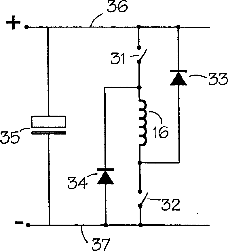
[0036] as attached Figure 8 One embodiment of an excitation circuit for exciting a switched reluctance motor has four active switches M A , M B , M C and M D , these switches are preferably MOSFET switches and are arranged around the phase winding 16 in a bridge configuration. The switches are capable of conducting current in a first direction and a second direction and are capable of operating as diodes. The direction of current flow through the phase winding...


PUM


Abstract

A switched reluctance machine is energized by phase circuits with four active switches, for example MOSFETs, arranged in a bridge configuration. The switches are capable of conducting current in both a first direction and a second direction and are capable of operating as a diode. The direction of current flow through the phase winding is reversed when changing from motoring to generating and from generating to motoring. The ratings of the switches are set in accordance with the energy supply and energy return currents.

Description

technical field [0001] The present invention relates to circuits for efficient operation of switched reluctance motors, particularly those motors required to operate in a monitoring mode and a generating mode. Background technique [0002] In general, a reluctance motor is one that produces torque by the tendency of its movable parts to move to a position where the reluctance of the magnetic circuit is minimized (ie, the inductance of the excitation winding is maximized). In some forms, circuitry is provided to detect the angular position of the rotor and to energize the phase windings as a function of the position of the rotor. This type of reluctance machine is often called a switched reluctance machine, and it can operate as a motor or a generator. The characteristics of such switched reluctance motors are also well known and described, for example, in "The Characteristics, Design and Application of Switched Reluctance Motors and Drives" by Stephenson and Blake (PCIM '93...

Claims


Application Information

Patent Timeline
Patent Type & Authority Applications(China)
IPC IPC(8): H02P25/08G11C29/00H02P6/00H02P6/14H02P27/06
CPCH02P25/085H02P9/40H02P25/092H02P25/08H02P27/06
Inventor 迈克尔·保罗·坦卡德
Owner NIDEC SR DRIVES
Why Eureka
Try Eureka