Process of absorbing detal gas from row material air flow
A nitrous oxide, gas flow technology, applied in the direction of nitrous oxide capture, chemical instruments and methods, through adsorption, etc.
- Summary
- Abstract
- Description
- Claims
- Application Information
AI Technical Summary
Problems solved by technology
Method used
Image
Examples
Embodiment 1
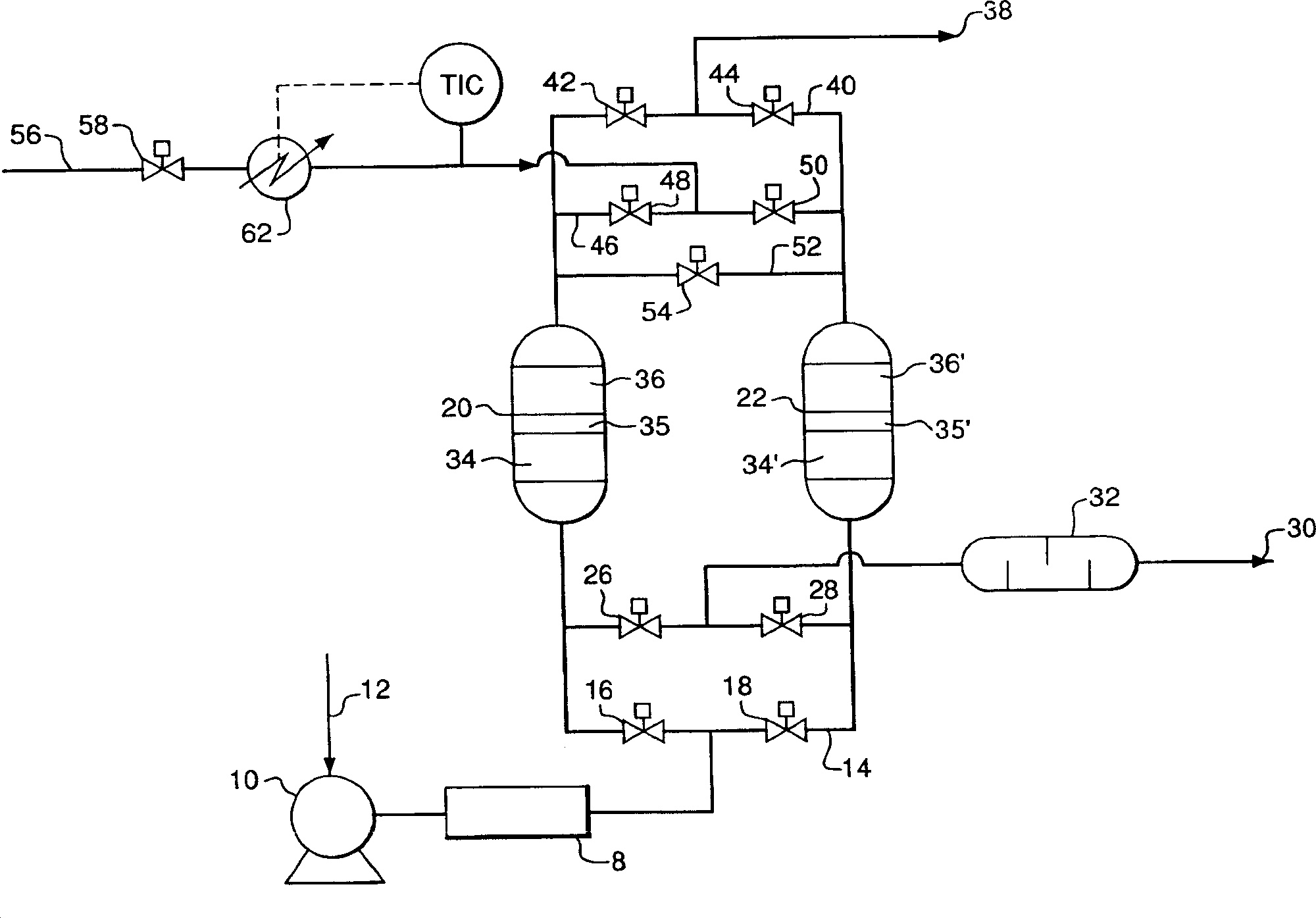
[0046] The same experiment was performed as described in Comparative Example A, except that NaX was used instead of CaX to fill the downstream 25% of the bed volume. The on-line time increased to 35 minutes (10 minutes heating, 19 minutes cooling, 6 minutes switchover) and the time-averaged carbon dioxide concentration in the bed effluent was essentially 0 ppb. In contrast to CaX, at a regeneration temperature of 70°C, the use of NaX will reduce the concentration of carbon dioxide in the bed effluent. In addition, the nitrous oxide removal capacity of the system was also measured. It was determined that the recycle and sorbent mixture removed 82% of the nitrous oxide entering the system (approximately 300 ppb inlet nitrous oxide). This nitrous oxide removal capability is suitable for cryogenic air separation processes where 80% nitrous oxide removal is acceptable.
Embodiment 2
[0048] The experiment described in Example 1 was carried out with the modification that: 30% by volume of silica gel, 30% by volume of alkali-treated alumina, 20% by volume of NaX and 20% by volume of 5A (CaA) zeolite were packed into the bed with layer 5A at the product end of the bed and silica gel at the feed end. On-line time increased to 37 minutes (10 minutes heating, 21 minutes cooling, 6 minutes switchover) and the time average carbon dioxide concentration in the bed effluent was 34 ppb. With this bed configuration, the nitrous oxide time-averaged effluent concentration is essentially 0 ppb, which corresponds to 100% nitrous oxide removal. It is clear that adding the 5A layer on top of the TSA improves the nitrous oxide removal capability of the system at low regeneration temperatures. Surprisingly, 5A gave good results for nitrous oxide removal, especially since Wenning's initial work on nitrous oxide removal in the TSA system clearly showed that 5A showed significan...
Embodiment 3
[0050] Carbon dioxide and dinitrogen monohydride isotherms were measured for all adsorbents tested in Comparative Example A and Examples 1 and 2. Isotherms were measured at 30°C after regeneration at 70°C in flowing nitrogen. Henry's law constants (initial isotherm slopes) and carbon dioxide / nitrous oxide selectivities (ratio of Henry's law constants) for carbon dioxide and nitrous oxide are given in Table 1 .
[0051] Adsorbent
[0052] From the results in Table 1 it is clear that materials with high nitrous oxide / carbon dioxide selectivity are not preferred for low temperature TSA removal of nitrous oxide from air. CaX has the highest carbon dioxide / nitrous oxide selectivity and is the preferred material for TSA as taught in US 6106593 as regenerated with high temperature. In addition, silica gel has high nitrous oxide / carbon dioxide selectivity, but its nitrous oxide capacity is too low to effectively remove trace amounts of nitrous oxide. Low temperature regene...
PUM
 Abstract
Description
Claims
Application Information
 - R&D
- Intellectual Property
- Life Sciences
- Materials
- Tech Scout
- Unparalleled Data Quality
- Higher Quality Content
- 60% Fewer Hallucinations
Browse by: Latest US Patents, China's latest patents, Technical Efficacy Thesaurus, Application Domain, Technology Topic, Popular Technical Reports.
© 2025 PatSnap. All rights reserved.Legal|Privacy policy|Modern Slavery Act Transparency Statement|Sitemap|About US| Contact US: help@patsnap.com

