Laminar flow arc plasma jet material surface processing method
A kind of arc plasma, plasma technology, applied in the direction of plasma, metal material coating process, coating, etc., can solve problems such as blank
- Summary
- Abstract
- Description
- Claims
- Application Information
AI Technical Summary
Problems solved by technology
Method used
Image

Examples
Embodiment 1
[0033] Example 1: Fusion surface strengthening treatment
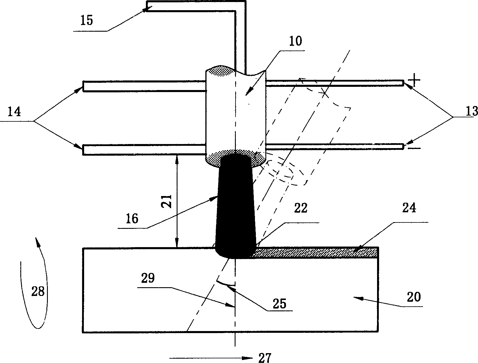
[0034] The Mo-W-Cu cast iron used for high-power diesel engine cylinder liners is subjected to single-scan fusion surface strengthening treatment by the treatment method of the present invention, and the relevant process parameters are: the air flow rate of the laminar plasma jet is 5 liters / min, The input power is 8kW, the distance between the workpiece and the generator outlet is 20mm, and the translation speed of the workpiece is 0.05m / min.
[0035] The results show that the laminar plasma jet heats the surface of the cast iron uniformly and is easy to operate and control. Even if the distance between the workpiece surface and the generator changes by 4 mm, the molten marks on the surface of the cast iron can be kept basically uniform, and the liquid in the molten pool can be maintained. There is no sign of being blown away from the molten pool by the jet. After the melting treatment, the graphite flakes in the molt...
Embodiment 2
[0036] Example 2: Powder injection type welding surface treatment
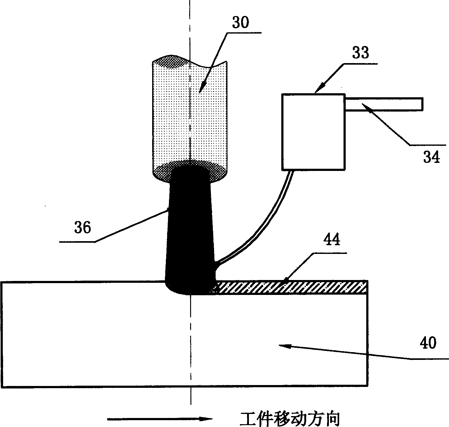
[0037] In this example, ZrO with a particle size of 40-100 μm is applied to the surface of 1Cr18Ni19Ti stainless steel. 2 Zirconia powder and 40% ZrO 2 - 60% Ni nickel-coated zirconia powder powder-injection deposition surface treatment. The relevant process parameters are: the laminar plasma jet working gas flow rate is 6 liters / min, the input power is 9kW, the distance between the workpiece and the generator outlet is 15mm, the workpiece moving speed is 0.1m / mim, and the powder supply gas flow rate is 0.3 liters / Minute.
[0038] The results show that a single treatment can form a cladding zone with a thickness of about 1mm and a width of about 4mm on the stainless steel surface. Microscopic observation shows that there is a good metallurgical bonding interface between the deposited layer and the workpiece substrate, and no micro-defects such as micro-cracks and micro-holes are generated. The microhardne...
Embodiment 3
[0039] Example 3: Preset powder type welding surface treatment
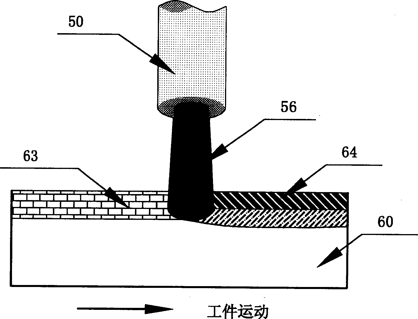
[0040] The pre-set powder type welding surface treatment method of the present invention is adopted. The selected base material, powder material and process parameters are completely the same as those in Example 2, the preset powder thickness is 0.1 mm, and the preset method is powder slurry painting.
[0041] The results show that the pre-cladding method can also form a cladding zone with a thickness of about 1 mm and a width of about 4 mm on the surface of stainless steel, and the same effect as that of the powder-injected cladding can be obtained. The difference is that this method does not involve a powder feeding process. In this way, for some fine powders with poor fluidity, such as ZrO with particle size less than 20 μm 2 Zirconia powder and 40% ZrO 2 -60% Ni nickel-coated zirconia powder, which can also be used for material surface strengthening treatment.
PUM
| Property | Measurement | Unit |
|---|---|---|
| Thickness | aaaaa | aaaaa |
| Width | aaaaa | aaaaa |
| Thickness | aaaaa | aaaaa |
Abstract
Description
Claims
Application Information
 - R&D
- Intellectual Property
- Life Sciences
- Materials
- Tech Scout
- Unparalleled Data Quality
- Higher Quality Content
- 60% Fewer Hallucinations
Browse by: Latest US Patents, China's latest patents, Technical Efficacy Thesaurus, Application Domain, Technology Topic, Popular Technical Reports.
© 2025 PatSnap. All rights reserved.Legal|Privacy policy|Modern Slavery Act Transparency Statement|Sitemap|About US| Contact US: help@patsnap.com