
Steel rail on-line ultrasonic flaw detecting method and apparatus thereof

A flaw detection device, ultrasonic technology, applied in measuring devices, using sound waves/ultrasonic waves/infrasonic waves to analyze solids, using sound waves/ultrasonic waves/infrasonic waves for material analysis, etc., can solve the problem of no stable device, small flaw detection coverage area, poor system stability, etc. problem, to achieve the effect of reducing labor intensity, adjustable detection range, stable and reliable walking

Inactive Publication Date: 2004-06-30
攀枝花钢铁有限责任公司
View PDF1 Cites 27 Cited by
  • Summary
  • Abstract
  • Description
  • Claims
  • Application Information

AI Technical Summary

Problems solved by technology

During use, a probe is arranged on the rail head side, rail waist and rail bottom, and the probe landing gear control is composed of relatively simple relays and proximity switches. This flaw detector has many shortcomings: 1. The flaw detection coverage area is small; 2. The blind area of ​​the rail end flaw detection is large, up to 300-500mm; 3. There is no continuous monitoring function of the interface or back echo signal; 4. The system stability is poor; 5. There is no data acquisition and automatic control device; 6. The debugging probe is not flexible ;7. One analog circuit flaw detector can only monitor one channel. If the rail with high flaw detection coverage area is required to be tested, many channels are needed to meet the coverage, and many instruments are required for monitoring.
However, there are still some defects in this device: the design of the combination probe is single, the probe is convenient to adjust, there is no stabilizing device in the process of rail walking, and the burrs and scales on the surface of the rail are easy to damage the probe wheel.

Method used


Image

  • Steel rail on-line ultrasonic flaw detecting method and apparatus thereof
  • Steel rail on-line ultrasonic flaw detecting method and apparatus thereof
  • Steel rail on-line ultrasonic flaw detecting method and apparatus thereof

Examples


Embodiment 1

[0030] An on-line ultrasonic flaw detection device for rails. The device includes a mechanical system, an information processing system and an automatic control system. Probe landing gear 3, probe frame adjustment mechanism 4 and marking device 5; information processing system includes digital ultrasonic flaw detector, waveform processing computer and waveform display; automatic control system includes probe landing gear 3, marking device 5 and speed measurement The three parts of the mechanism 2, wherein the control part of the probe landing gear 3 and the marking device 5 is composed of a proximity switch 6, a photoelectric rotary encoder 7, a PLC controller, an electrical control computer and its display.

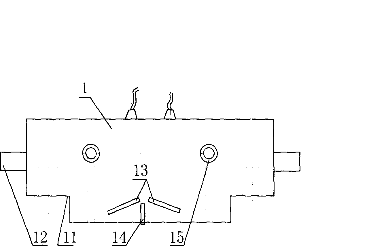
[0031] The coupling mode of the multi-chip probe 1 adopts the direct contact method. The multi-chip probe 1 includes a water tank 11, an installation shaft 12, and a wafer 13, and also includes a sound insulation layer 14 between the wafers 13, and a water inlet 15 is arr...

Embodiment 2

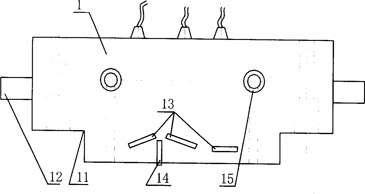
[0037] An on-line ultrasonic flaw detection device for rails, the structures of the device's speed measuring mechanism 2, contact-coupled probe lift 3 and probe holder adjustment mechanism 4 are the same as those in Embodiment 1, but the number of probe chips is 3 (attached image 3 ).

[0038] Coverage area (%)


PUM


Abstract

The invention discloses a kind of online supersonic wave detection method and the device for steel track. The device comprises mechanical system, information processing system and the automatic control system, the mechanical system is made up of steel rail guiding mechanism, steel rail guiding and restraining mechanism, multi-crystal supersonic detecting head, speed measuring mechanism, two sets of contacting coupled detecting head landing chassis, detecting frame adjustment mechanism and mark spraying device; information processing system includes digital supersonic wave detection instrument, waveform processing computer and the waveform monitor; the automatic control system includes detecting head landing chassis, mark spraying and speed measuring, made up of closing switch, photoelectric rotary coding device, PLC controller, electricity control computer and the monitor.

Description

technical field [0001] The invention belongs to the technical field of non-destructive testing of steel rails, and in particular relates to an on-line flaw detection method and a device for steel rails using ultrasonic pulse wave reflection detection technology. Background technique [0002] With the development of railway transportation in the direction of high-speed and heavy-duty, the requirements for the quality of rail products are getting higher and higher. Flaw detection of the internal quality of rails before leaving the factory is a necessary process for rail manufacturers, and the scanning area for rail flaw detection is getting higher and higher. The head part is not less than 70%, and the rail waist part is not less than 60%. [0003] Ultrasonic testing technology is a kind of non-destructive flaw detection, which has the advantages of not destroying the inspected workpiece, fast detection speed, relatively low flaw detection cost, and easy to realize online fla...

Claims


Application Information

Patent Timeline
Patent Type & Authority Applications(China)
IPC IPC(8): G01N29/04
CPCG01N2291/044
Inventor 李杨辉李高龙战金龙赵国立范方灵王彦中梅东生陈朝明曾富顾延风
Owner 攀枝花钢铁有限责任公司
Learn More