Radio frequency pulse angle phase setting method and circuit thereof

A radio frequency pulse, right angle technology, applied in the field of radio frequency pulse right angle phase setting and circuit, can solve the problem of no right angle phase setting function, etc., to achieve the effect of no DC component, accurate modulation, and easy implementation

Inactive Publication Date: 2004-07-07
SHENZHEN ANKE HIGH TECH CO LTD
View PDF0 Cites 1 Cited by
  • Summary
  • Abstract
  • Description
  • Claims
  • Application Information

AI Technical Summary

Problems solved by technology

[0014] The object of the present invention is to provide a method, which can solve the problem of using a single-chip direct digital synthesizer (DDS) in an MRI system, and this type of DDS chip has neither a right-angle phase setting function nor an external setting for a right-angle phase setting. When setting up the interface, the problem of setting the right-angle phase for the RF pulse

Method used


Image

  • Radio frequency pulse angle phase setting method and circuit thereof
  • Radio frequency pulse angle phase setting method and circuit thereof
  • Radio frequency pulse angle phase setting method and circuit thereof

Examples


Embodiment Construction

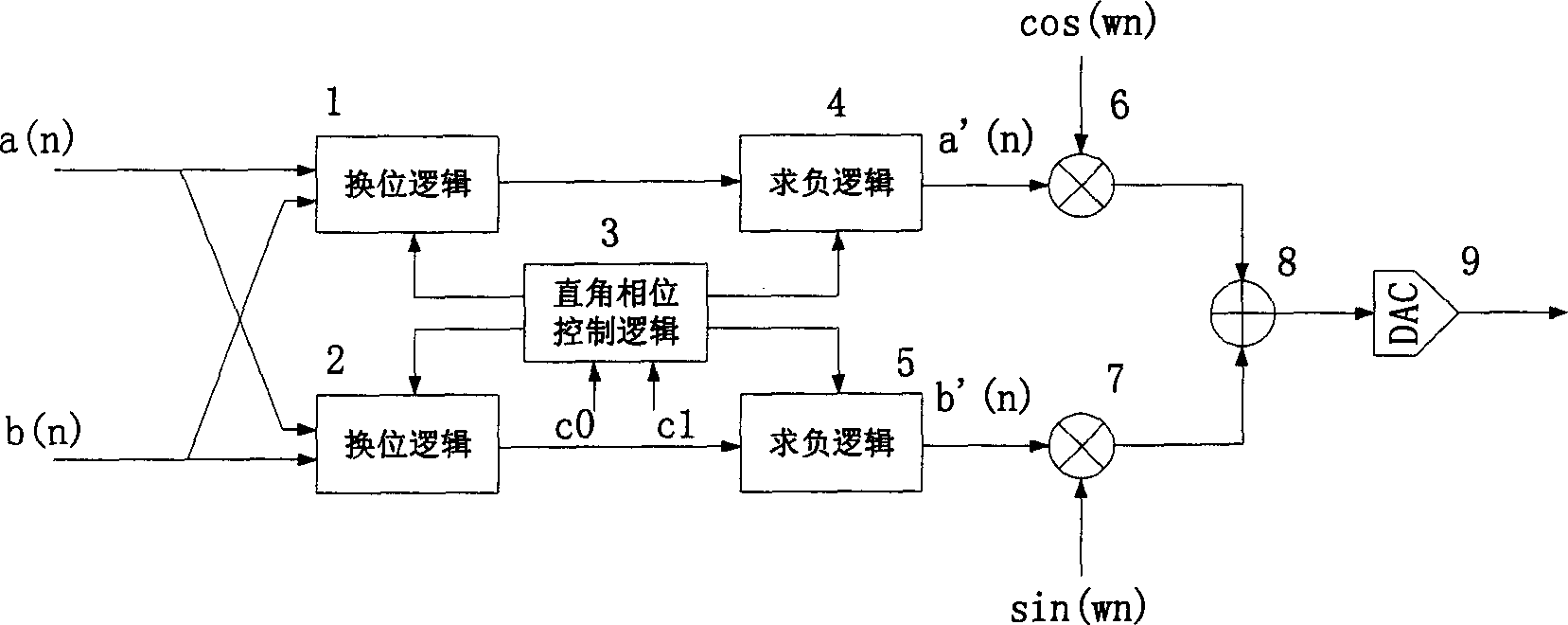
[0050] Such as figure 2 As shown, a(n) and b(n) are digitized complex envelope signals, a'(n) and b'(n) are digitized complex envelope signals after phase setting, and C0 and C1 are right-angle phase control signal, when the right-angle phase control signals C0 and C1 are combined with different codes, figure 2 The working states of the functional modules shown are different, and the results of the digitized complex envelope signals a'(n) and b'(n) obtained after phase setting are also different, a'(n), b'(n) and DDS The digitized carrier frequency cos(ωn) and sin(ωn) signals of the output are multiplied correspondingly in the digital multipliers 6 and 7, and then added in the adder 8, so that the right angle phase of the radio frequency pulse is 0°, 90°, 180°, 270° settings. The relationship between the setting of the right-angle phase control signals C0 and C1 and the working status of each module and the results of the obtained digitized complex envelope signals a'(n) a...


PUM


Abstract

In the present invention, transposition and complementing for envelope signal can be achieved by utilizing trigonometrical function transform when 90 degree, 180 degree and 270 degree set for carrier right angle phase is changed-over to zero degree phase so that problem which there is no function of right angle phase and no function of processing ability for carrier output in some synthesizers of single chip direct digital frequency type can be solved.

Description

field of invention [0001] The invention relates to a method and a circuit for setting a radio frequency (RF) pulse phase in a magnetic resonance imaging (MRI) system. Background technique [0002] In the MRI system, RF pulses modulated in the following form are used (assuming that the initial phase is 0, the same below): [0003] a(t)cos(ωt+φ)+b(t)sin(ωt+φ)………(1) [0004] Among them, a(t)+jb(t) is the complex envelope signal, cos(ωt+φ)+j sin(ωt+φ) is the complex carrier signal, ω is the RF pulse carrier frequency, and φ is the RF pulse carrier phase. In the MRI imaging sequence (sequence), the right-angle phase setting is often used, that is, φ is set to 0°, 90°, 180°, 270°. [0005] When using a direct digital frequency synthesizer (DDS) to generate RF pulses, there are usually only 1 / 4 cycle cos and sin tables in the DDS, and a complete cycle can be output using symmetry. In this RF pulse generation method, the following trigonometric transformation is used: [0006] c...

Claims


Application Information

Patent Timeline
Patent Type & Authority Applications(China)
IPC IPC(8): G01R33/32H03L7/00
Inventor 胡曾千臧继运邢研
Owner SHENZHEN ANKE HIGH TECH CO LTD
Why Eureka
Try Eureka