Piezoelectric body, mfg. method thereof, piezoelectric element having piezoelectric body, inkjet head and inkjet type recording device
A manufacturing method and piezoelectric technology, which are applied in the manufacture/assembly of piezoelectric/electrostrictive devices, piezoelectric devices/electrostrictive devices, piezoelectric/electrostrictive/magnetostrictive devices, etc., can solve the problem. Deterioration, etc.
- Summary
- Abstract
- Description
- Claims
- Application Information
AI Technical Summary
Problems solved by technology
Method used
Image

Examples
Embodiment approach 1
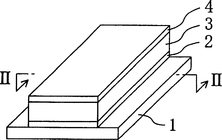
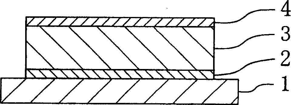
[0049] figure 1 and figure 2 A piezoelectric element representing a piezoelectric body 3 according to an embodiment of the present invention, the piezoelectric element includes a first electrode 2 provided on a substrate 1, the above-mentioned piezoelectric body 3 provided on this first electrode 2, and a piezoelectric body provided on this piezoelectric element. The second electrode 4 on the electric body 3.
[0050] The above-mentioned substrate 1 is made of, for example, silicon (Si) with a thickness of 0.2 mm, and the above-mentioned first and second electrodes 2 and 4 are made of, for example, platinum (Pt) with a thickness of 0.1 μm.
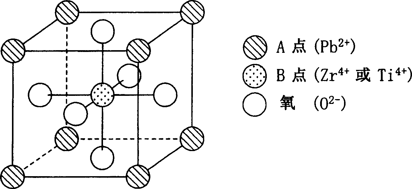
[0051] The above-mentioned piezoelectric body 3 is made of a piezoelectric material mainly composed of lead (Pb), zirconium (Zr) and titanium (Ti), and has a general formula ABO 3 This shows a perovskite crystal structure in which the main component of point A is Pb, and the main components of point B are Zr, Ti, and Pb. That is to sa...
Embodiment approach 2
[0084] Figure 5 and Figure 6 Indicates an inkjet head according to an embodiment of the present invention. This inkjet head includes a plurality of piezoelectric bodies 13 similar to those described in Embodiment 1 above, and a pair of first piezoelectric bodies 13 respectively provided on both sides in the thickness direction of the piezoelectric body 13. As well as the second electrodes 12 and 14 (the same as the first and second electrodes 2 and 4 described in Embodiment 1), the electrode on this side (the first electrode 12) on the opposite side to the piezoelectric body 13 The vibrating plate 15 provided on one side (lower surface) and the pressure chamber member 16 for forming the pressure chamber 20 for containing ink are joined to the surface (lower surface) of the vibrating plate 15 opposite to the first electrode 12 . In this embodiment, the plurality of piezoelectric bodies 13 are provided at 200 per inch.
Embodiment approach 3
[0096] Figure 7 An inkjet recording device according to an embodiment of the present invention is shown, and this inkjet recording device has the same inkjet head 28 as that in Embodiment 2 described above. The structure is such that, in this inkjet head 28, the pressure is applied from the nozzle hole (nozzle hole 23 in the above-mentioned embodiment 2) provided to communicate with the pressure chamber (the pressure chamber 20 in the above-mentioned embodiment 2). The ink in the chamber is ejected onto the recording medium 29 (recording paper or the like) to perform recording.
[0097] The above-mentioned inkjet head 28 is mounted on a holder 31 provided on a holder shaft 30 along the main scanning direction X. . Thus, the carriage 31 constitutes a relative movement device for relatively moving the inkjet head 28 and the recording medium 29 along the main scanning direction X. As shown in FIG.
[0098] This inkjet recording device has a plurality of rollers 32 for moving ...
PUM
| Property | Measurement | Unit |
|---|---|---|
| thickness | aaaaa | aaaaa |
| thickness | aaaaa | aaaaa |
| thickness | aaaaa | aaaaa |
Abstract
Description
Claims
Application Information
 - R&D
- Intellectual Property
- Life Sciences
- Materials
- Tech Scout
- Unparalleled Data Quality
- Higher Quality Content
- 60% Fewer Hallucinations
Browse by: Latest US Patents, China's latest patents, Technical Efficacy Thesaurus, Application Domain, Technology Topic, Popular Technical Reports.
© 2025 PatSnap. All rights reserved.Legal|Privacy policy|Modern Slavery Act Transparency Statement|Sitemap|About US| Contact US: help@patsnap.com