Eccentric rotation shaft and electric motor shaft mfg. method

A technology of eccentric shafts and manufacturing methods, which is applied to eccentric shafts, shafts and bearings, rotary piston machines, etc., can solve the problems of reducing product wear resistance, product quality, and productivity, and achieve outstanding wear resistance, Reduced production time and long service life

A technology of eccentric shafts and manufacturing methods, which is applied to eccentric shafts, shafts and bearings, rotary piston machines, etc., can solve the problems of reducing product wear resistance, product quality, and productivity, and achieve outstanding wear resistance, Reduced production time and long service life

CN1515804AInactive Publication Date: 2004-07-28金英基

Image

  • Eccentric rotation shaft and electric motor shaft mfg. method
  • Eccentric rotation shaft and electric motor shaft mfg. method
  • Eccentric rotation shaft and electric motor shaft mfg. method

Examples


Embodiment Construction

[0021] How the present invention is realized is further described below through specific embodiments.

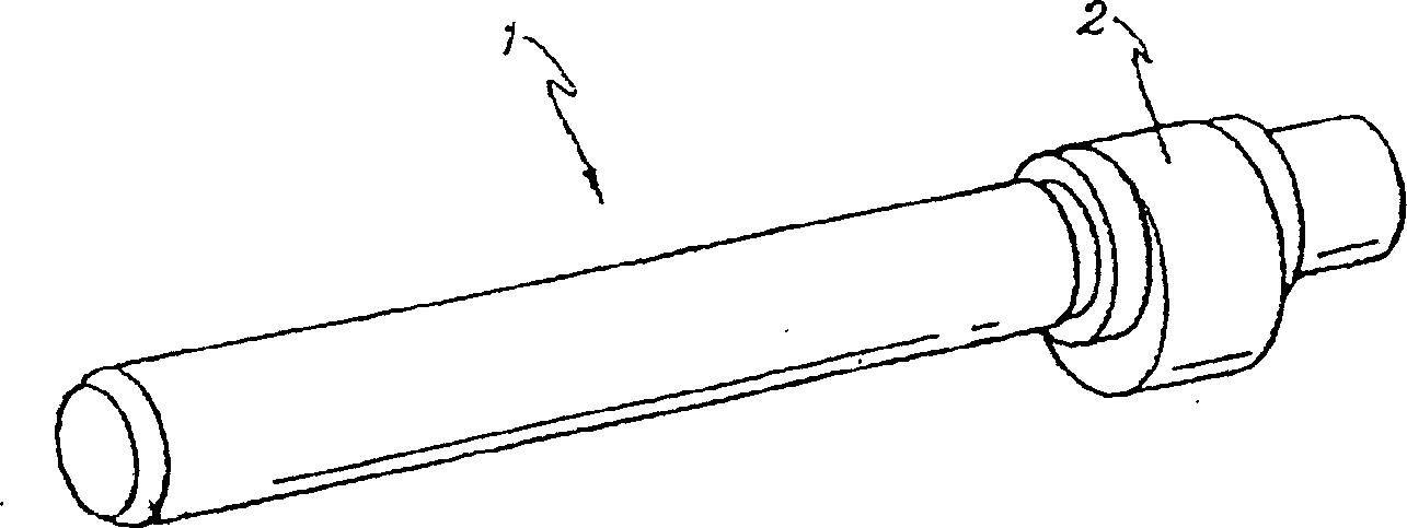
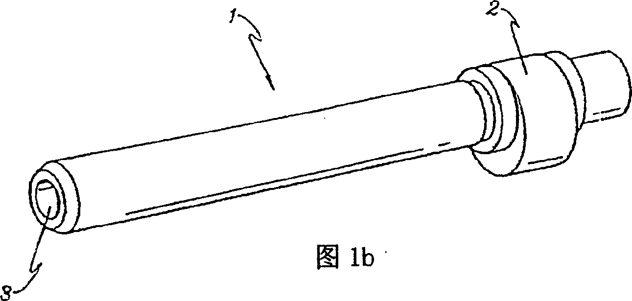
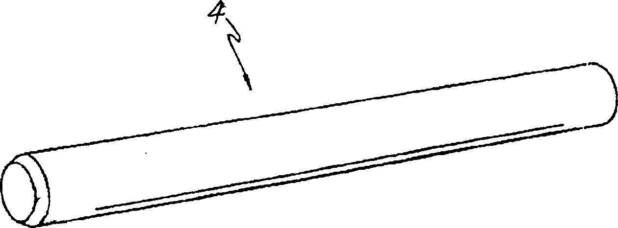
[0022] The present invention firstly solves the problems of the traditional manufacturing method in the manufacturing method (porosity is generated, the wear resistance is reduced) and the problems caused by the complicated working procedure. In the traditional manufacturing method, the long axis is drilled with a deep hole to form a flow hole to allow the refrigerant to flow. In the invention, the steel plate is processed into a long-axis tube through the tube-making operation, and then the steel tube is stretched and cut according to the specifications through the stretching process instead of the traditional turning process. Afterwards, the rotor is formed on the cut shaft through a forging process, and the final eccentric shaft is an important feature.

[0023] The specific steps of the manufacturing method of the eccentric shaft of the present invention are as follows:...


PUM


Abstract

The manufacturing method of crank shaft comprises a pipe making process; a drawing process; a cutting process; a forging process; and a processing process. The manufacturing method of crank shaft also could only comprise a pipe making process; a cutting process; a forging process; and a processing process. The manufacturing method of motor shaft comprises a pipe making process; a drawing process; a cutting process; and a processing process of forming a key groove on the motor shaft finally completed through the cutting process.

Description

technical field [0001] The invention relates to a manufacturing method of a shaft, in particular to a manufacturing method of an eccentric shaft and a motor shaft used in an air-conditioning compressor. Background technique [0002] Generally speaking, the eccentric shaft plays the role of converting reciprocating motion into rotary motion. As shown in FIG. 1, an eccentric rotor 2 is formed at a selected position on one side to connect the corresponding ends of the connecting rods, while the outer side of the eccentric rotor 2 is formed into a cylindrical shape. Bearings will be loaded onto the eccentric shaft 1 to convert sliding friction into rotational friction, thereby reducing motion resistance. In addition, after the axial direction of the eccentric shaft 1 is perforated, the circulation hole 3 is formed to allow the refrigerant to circulate. [0003] As shown in FIG. 2 , the general motor shaft 4 is formed in the shape of a pipe rod, and its axial direction is perfo...

Claims


Application Information

Patent Timeline
28 Jul 2004
Publication
CN1515804A
IPC
B21K1/08; F04C18/00; F16C3/02; F16C3/18
CPC
B21C37/08; B21J5/10; B21J5/12; B21K1/08; C21D9/08
Inventors
金英基