Synchronuos reluctance motor control device

A technology of synchronous reactance and control devices, which is applied in the direction of motor control, electronic commutation motor control, motor generator control, etc., to achieve the effects of vibration, low noise, and suppression of torque fluctuations

Inactive Publication Date: 2004-07-28
PANASONIC CORP
View PDF1 Cites 26 Cited by
  • Summary
  • Abstract
  • Description
  • Claims
  • Application Information

AI Technical Summary

Problems solved by technology

[0011] It is an object of the present invention to solve these conventional problems and to provide a control device for a sync

Method used


Image

  • Synchronuos reluctance motor control device
  • Synchronuos reluctance motor control device
  • Synchronuos reluctance motor control device

Examples


Embodiment Construction

[0044] Next, preferred embodiments of a control device for a synchronous reactance motor according to the present invention will be described with reference to the drawings.

[0045] Embodiment 1

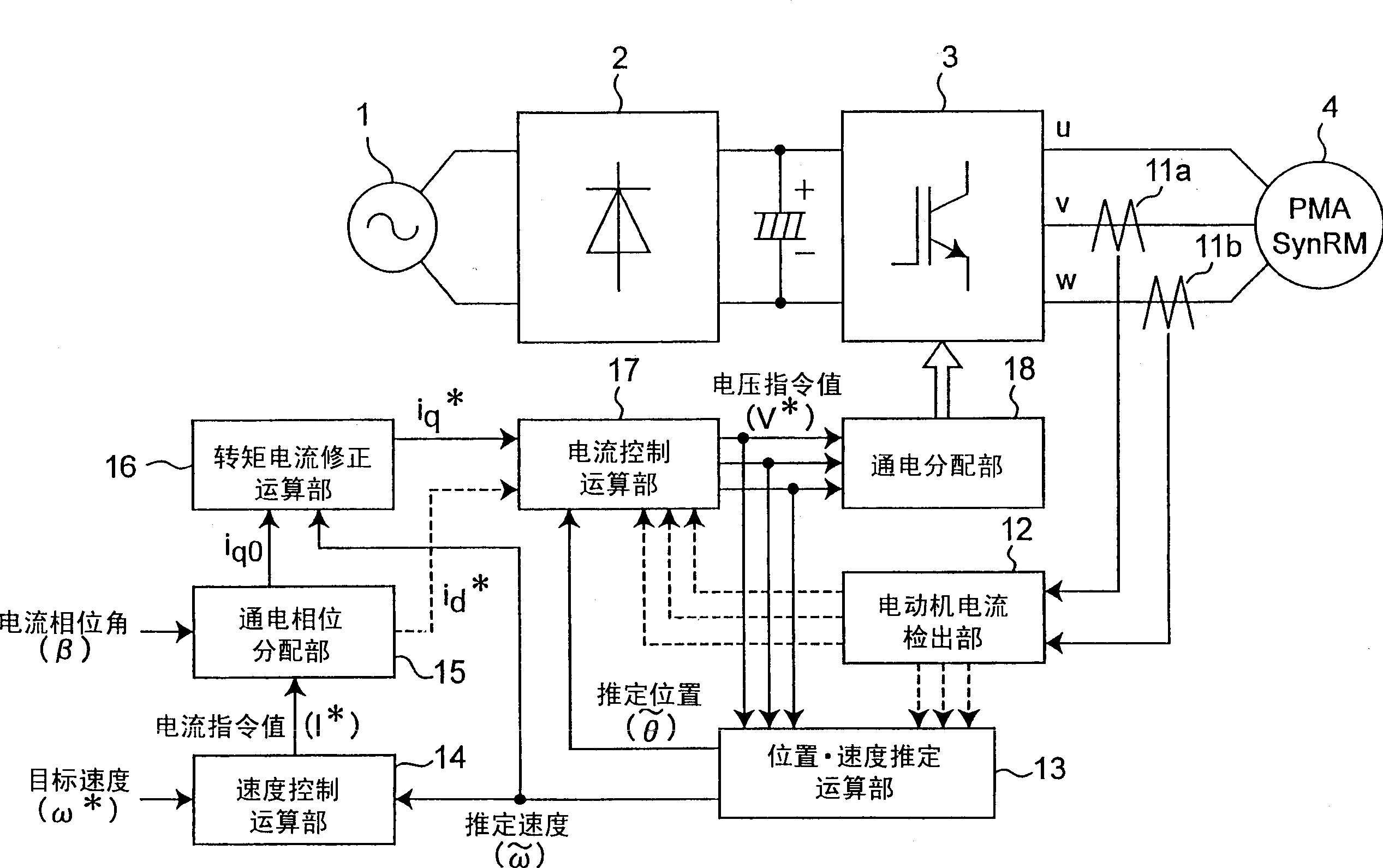
[0046] figure 1 It is a figure which shows an example of the whole structure of the control apparatus of the synchronous reactance motor (SRM) of this invention. Furthermore, an example will be described below in which a permanent magnet-assisted synchronous reactor motor is driven with a sine wave by 180-degree energization without using a position sensor.

[0047] The main circuit consists of an AC power supply 1, an AC / DC converter 2 that converts AC power to DC power, a DC / AC converter 3 that converts DC power into AC power, and a permanent magnet that is driven by the AC power converted by the DC / AC converter 3 Auxiliary synchronous reactance motor 4 constitutes.

[0048]The control circuit is composed of current detectors 11a and 11b for detecting the motor current, a moto...


PUM


Abstract

A control apparatus of a synchronous reluctance motor includes a torque current correction unit (16) that generates a torque current command tracing a load torque so as to make the output torque of the motor coincide with the load torque. the control apparatus may further include a position and speed estimation unit (13) that estimates the position and speed based on three phase voltage equation to improve control performance in a voltage saturation state.

Description

technical field [0001] The present invention relates to a control device for a synchronous reactance motor, and more particularly to a control device that estimates the angle of a rotor without using a position sensor and drives the motor. Background technique [0002] A conventional control device for a synchronous reactance motor obtains angle information of a rotor using a Hall element, a resolver, or a position sensor of an optical encoder. Therefore, the cost of the position sensor is increased, and the size of the control device of the synchronous reactance motor is also increased. [0003] Therefore, as a control device for a synchronous reactance motor that realizes a low-cost and compact synchronous reactance motor by omitting a position sensor, generally known devices such as Figure 23 The control device of the synchronous reactance motor shown. [0004] exist Figure 23 Among them, the main circuit is driven by AC power source 1, AC / DC converter 2 for converting...

Claims


Application Information

Patent Timeline
IPC IPC(8): H02P21/00H02P21/05H02P21/14H02P21/18H02P21/22H02P21/24H02P21/28H02P23/04H02P23/14H02P23/16H02P23/18H02P25/08H02P27/04H02P29/00
CPCH02P25/085H02P25/083H02P25/089H02P25/092
Inventor 河地光夫松城英夫松井敬三
Owner PANASONIC CORP
Why Eureka
Try Eureka