Sintered alloy valve seat and its manufacturing method

A technology of alloy and valve seat, applied in the field of manufacturing this valve seat, can solve the problems of high manufacturing cost, wear of valve and valve seat, complicated steps of increasing density, etc., and achieve the effect of low cost

Active Publication Date: 2004-08-04
NIPPON PISTONRING CO LTD +1
View PDF2 Cites 32 Cited by
  • Summary
  • Abstract
  • Description
  • Claims
  • Application Information

AI Technical Summary

Problems solved by technology

Therefore, there is a problem that the manufacturing method is complicated and the manufacturing cost is high
In the technique disclosed in Patent Document 3, in order to reduce the porosity of the base portion, a step of subjecting the sintered compact to compression forging by a rotary forging process and a step of subjecting the resulting sintered compact to resintering are necessary, and therefore, there is The problem is that the manufacturing method is complicated and the manufacturing cost is high
However, the steps to increase density are more complex
Therefore, there is a problem that the manufacturing cost is high
Therefore, there is a problem that the valve and the seat will wear heavily

Method used


Image

  • Sintered alloy valve seat and its manufacturing method
  • Sintered alloy valve seat and its manufacturing method
  • Sintered alloy valve seat and its manufacturing method

Examples


Embodiment

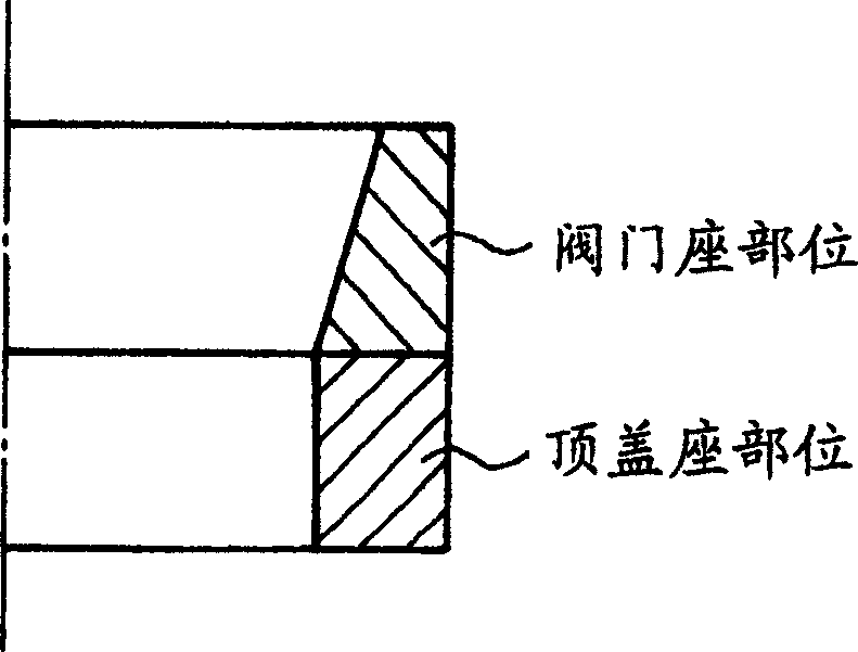
[0076] Pure iron powder, hard particle powder and iron alloy powder and / or alloy element powder are mixed in the ratio shown in Table 1, and the types of these powders are shown in Table 1. Moreover, a predetermined amount (by weight) of solid lubricant particles is added to 100 parts (by weight) of a mixture of pure iron powder, hard particle powder and iron alloy powder and / or alloy element powder, and the resulting mixture Mix, then knead. Thereby, the first raw material powder for making the valve seat part and the second raw material powder for making the top cover seat part are obtained. In addition to the solid lubricant particle powder, pure iron powder, hard particle powder and iron alloy powder and / or alloy element powder are expressed by mass percentage. Sample 18 is a comparative example without solid lubricant particle powder.

[0077] sample

part

Powder composition (% mass)

solid lubricant

granular powder

raw briquette...


PUM

PropertyMeasurementUnit
densityaaaaaaaaaa
densityaaaaaaaaaa
hardnessaaaaaaaaaa

Abstract

A valve seat, press-fitted into a cylinder head of an internal combustion engine, containing an iron-based sintered alloy, includes a valve-seating section and a head-seating section. The valve-seating section and the head-seating section are monolithically formed by a sintering process and form a double layer structure. The valve-seating section includes a first iron-based sintered alloy member that has a porosity of 10 to 25 percent by volume and a sintered density of 6.1 to 7.1 g / cm<3> and contains hard particles dispersed in a matrix. The head-seating section includes a second iron-based sintered alloy member that has a porosity of 10 to 20 percent by volume and a sintered density of 6.4 to 7.1 g / cm <3>.

Description

technical field [0001] The invention relates to valve seats for internal combustion engines. In particular, the present invention relates to a valve seat made of iron-based sintered alloy having high wear resistance and a method of manufacturing the valve seat. Background technique [0002] A valve seat press-fitted into the cylinder head of an engine has been used to prevent the leakage of combustion gases and to cool the valve. These seats must be highly resistant to heat, wear and corrosion, while having low reverse erosion properties to avoid galling of the opposing valve. [0003] With regard to automobile engines, improvements in life, power, gas emission, fuel efficiency, and the like have recently been demanded. Therefore, valve seats for these automotive engines must be able to be used in harsher environments than before. Therefore, the heat resistance and wear resistance of the valve seat must be further improved. [0004] In order to meet these needs, Japanese...

Claims


Application Information

Patent Timeline
Patent Type & Authority Applications(China)
IPC IPC(8): B22F1/00B21K1/24B22F3/035B22F5/00B22F7/00B22F7/06C22C38/00F01L3/02
CPCF01L2103/00Y10T29/49306B22F7/06F01L3/02F01L2101/00B22F5/008B21K1/24B22F2998/00F01L2301/00F01L2303/00
Inventor 佐藤贤一垣内新高桥辉夫石田正雄桶谷裕之
Owner NIPPON PISTONRING CO LTD
Why Eureka
Try Eureka