Microarray biochip reflective image obtaining and analysis device and method

An image acquisition device and biochip technology, which is applied in the field of microarray image acquisition, can solve the problems of slow acquisition of deep-well microarray images, uneven luminosity of holes in porous discs, and large image reading area, etc. Acquire time, correct chiaroscuro, improve image distortion effects

Inactive Publication Date: 2004-08-18
DR CHIP BIOTECH
View PDF1 Cites 13 Cited by
  • Summary
  • Abstract
  • Description
  • Claims
  • Application Information

AI Technical Summary

Problems solved by technology

[0012] The technical problem to be solved by the present invention is the problem of non-uniform and insufficient luminosity in the hole of the porous disk before the reflective image is acquired in the prior art; secondly, the speed of acquiring the image of the deep-hole microarray is too slow; moreover, the deep-hole microarray The image reading area is too large during image acquisition, resulting in distortion of the acquired image

Method used


Image

  • Microarray biochip reflective image obtaining and analysis device and method
  • Microarray biochip reflective image obtaining and analysis device and method
  • Microarray biochip reflective image obtaining and analysis device and method

Examples


Embodiment Construction

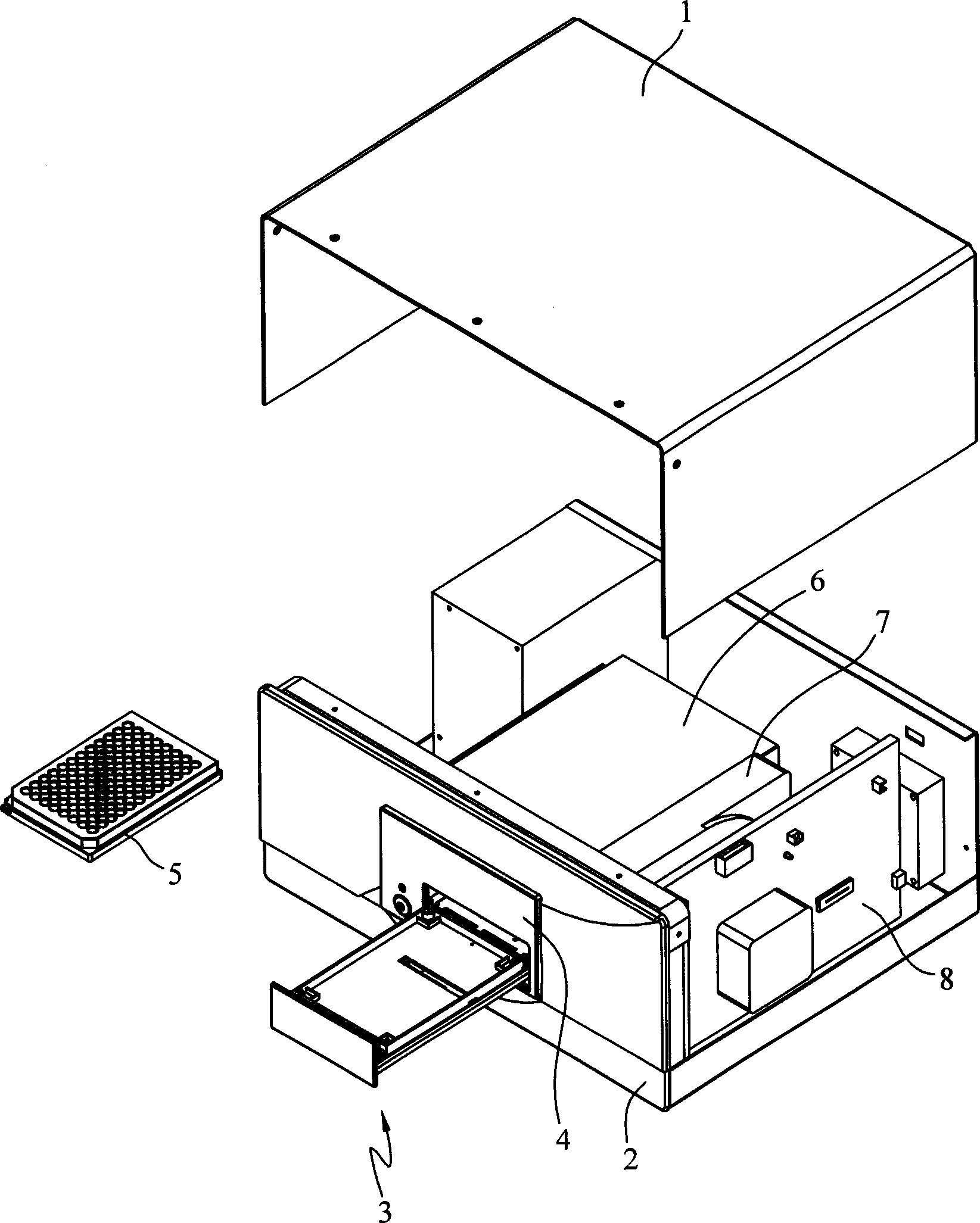
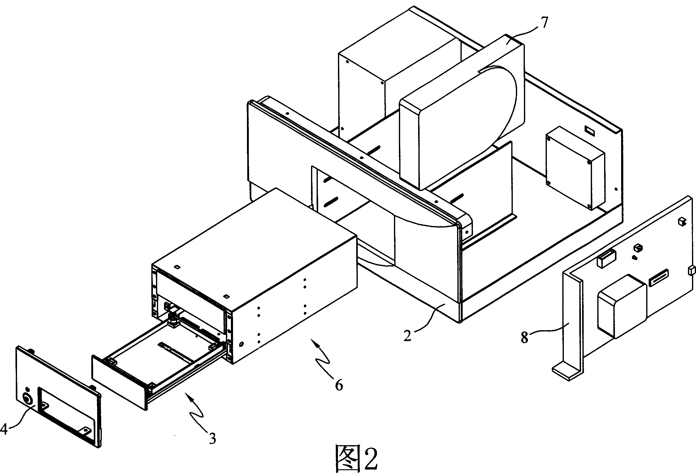
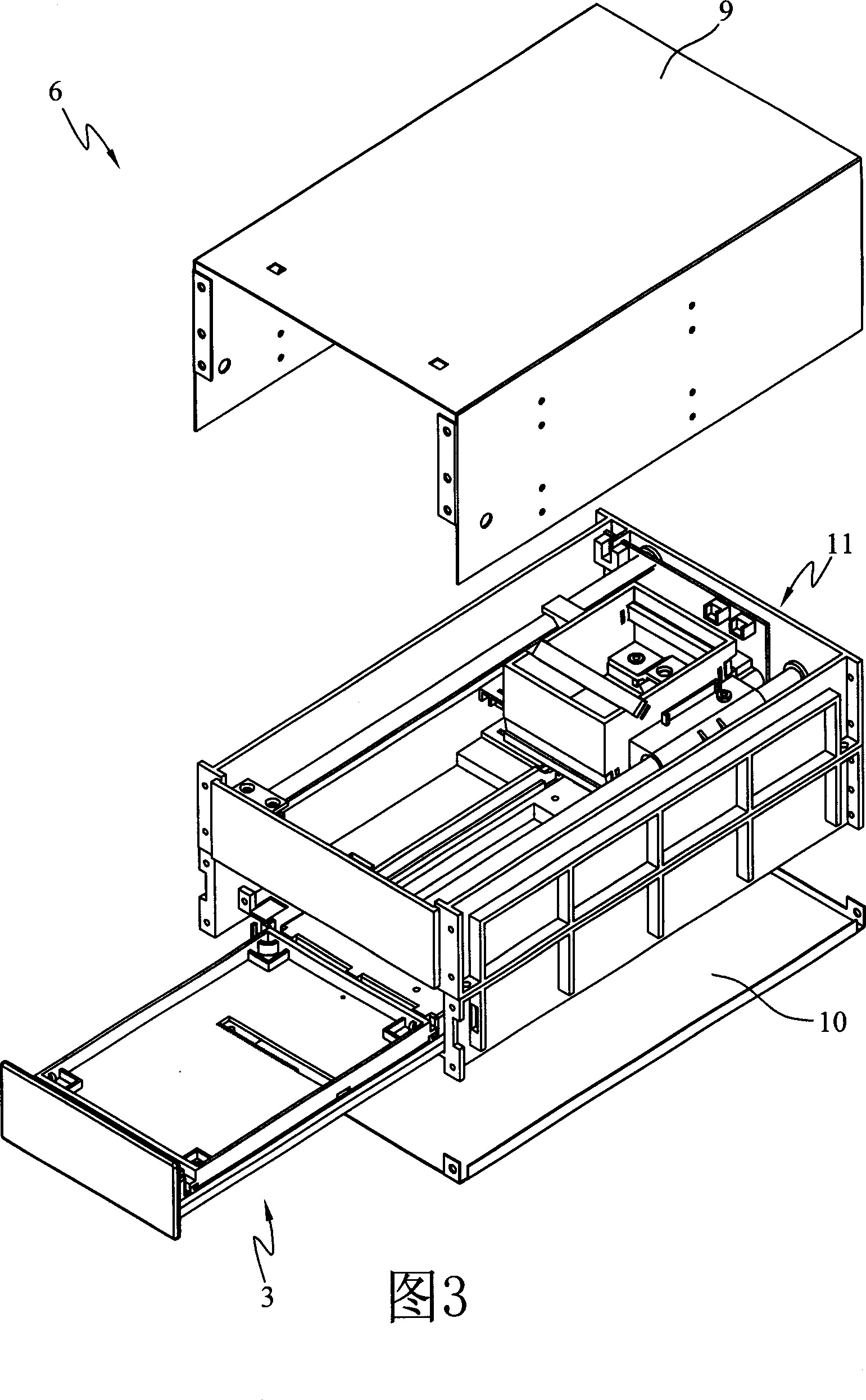
[0072] Figure 1 to Figure 6 It is a preferred embodiment of the present invention, including schematic diagrams of an image acquisition device in different disassembled states. The following matching icons describe in detail the composition and matching relationship of the components of the image acquisition device:

[0073] figure 1 It is a three-dimensional schematic diagram of dismantling the first layer of the image acquisition device. After the upper cover 1 is lowered to cover the bottom case 2, the chassis of the complete device is formed. There is an opening on the front of the case for the drawer tray 3 to enter and exit; the drawer tray 3 can be sucked in or pushed out through the entrance. figure 1 It is a schematic diagram after the drawer tray 3 is pushed out (see Figure 5 for further disassembly of the drawer tray 3). The 4 rings of the decorative plate are pasted on the outer edge of the tray entrance, which is used for identification and beautification o...


PUM


Abstract

The present invention relates to an apparatus and a method for accessing and processing a reflection image from a microwell-plate-based biochip. The invented apparatus uses a mobile system for carrying a photo device and a multi-apertured tray for relative displacements in various directions. Therefore, the micro-array reflection images in all holes of the multi-apertured tray are obtained in a single scanning process, and a computer program is used to compare the image data with predetermined patterns for analysis.

Description

technical field [0001] The present invention relates to an image acquisition and analysis device and method for a microarray biochip, in particular to the acquisition of colorimetric microarray images in a microplate. Background technique [0002] Biochip or microarray is a very effective technology to solve multiple analytes in parallel. It has been widely used in the field of research, and there are also kits for microbial or genetic testing. However, a large amount of information presented by the biochip after operation and reaction must be combined with a biochip signal detection and analysis system that can obtain multiple data at the same time, in order to achieve the purpose of biochip to analyze a large amount of information at one time. [0003] At present, most general-purpose microarrays or biochips use the specifications of glass slides as flat carriers, and multiple nucleic acid or protein matrix points are immobilized on the surface as detection probes to detec...

Claims


Application Information

Patent Timeline
Patent Type & Authority Applications(China)
IPC IPC(8): B01L3/00C12Q1/68C40B40/06G01N15/00G01N15/14G01N21/25G01N21/64G01N35/02
CPCG01N15/1475G01N21/6428G01N21/6452C12Q1/689C40B40/06G01N21/6456G01N35/028B01L3/5085B01J2219/00529B01J2219/00704B01J2219/00722G01N2015/0088C12Q1/6837C12Q2531/113C12Q2565/531
Inventor 林嘉柏陈建安陈孟钰黄明远王涵威白家瑄
Owner DR CHIP BIOTECH
Why Eureka
Try Eureka