Manufacturing method for non-aqueous electrolyte secondary battery and used electrode thereof

A non-aqueous electrolyte, secondary battery technology, applied in the direction of non-aqueous electrolyte storage battery electrodes, non-aqueous electrolyte storage batteries, secondary battery manufacturing, etc., can solve problems such as reduced productivity, and achieve the effect of easy manufacturing

Inactive Publication Date: 2004-09-01
SANYO ELECTRIC CO LTD
View PDF2 Cites 45 Cited by
  • Summary
  • Abstract
  • Description
  • Claims
  • Application Information

AI Technical Summary

Problems solved by technology

[0021] In addition, the insulating adhesive tape, which has been used to prevent short circuits, is frequently cleaned because the adhesive adheres to the manufacturing equipment during the electrode manufacturing process such as the electrode plate cutting process and the electrode body forming process. , so that there is a problem of lower productivity

Method used


Image

  • Manufacturing method for non-aqueous electrolyte secondary battery and used electrode thereof
  • Manufacturing method for non-aqueous electrolyte secondary battery and used electrode thereof
  • Manufacturing method for non-aqueous electrolyte secondary battery and used electrode thereof

Examples


Embodiment 1~3、 comparative example 1~2

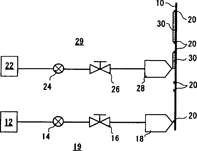
[0053] As Examples 1-3 and Comparative Examples 1-2, as figure 2 As shown, the insulating layer was manufactured by resin coating and drying method. First, a wide aluminum foil roll (not shown) commonly used as a positive electrode core (collector) is prepared so that it can be rolled from figure 2 move continuously from bottom to top. A 20% solution of polyvinylidene fluoride (PVdF) dissolved in N-methylpyrrolidone (NMP) solution is used as the coating resin 12. The insulating layer forming device 19 constituted by a die coater 18 is extruded and coated by a predetermined length at predetermined intervals to form the insulating layer 20 . Change the coating amount by controlling the gear pump 14, and change the thickness of the insulating layer 20 to 5 μm (comparative example 1), 10 μm (embodiment 1), 50 μm (embodiment 2), 180 μm (embodiment 3) and 300 μm (comparative example Example 2) Five types of samples were produced, and the electromagnetic valve 16 was electricall...

Embodiment 4、 comparative example 4

[0059] As Example 4, resin coating of the insulating layer was carried out at the time of manufacturing the positive electrode plate by the hot-melt method. That is, if Figure 4 As shown, a coating resin in which 95 parts of polypropylene and 5 parts of water-added □□□□ (trade name) resin were dissolved and mixed at 200° C. was melted with a heating and melting device 32 heated to 180° C. Control the amount of coating, while extruding through the switching solenoid valve 36 and the heating die slot (dieslot) 38, before and after the positive electrode active material mixture layer 42 of a specific length that is intermittently formed on the positive electrode core 40, an insulating layer is formed. Layer 44. Furthermore, the control of the coating position and coating length is performed while electrically controlling the switching solenoid valve 36 using a position detector (not shown), so that they are kept constant. The insulating layer 44 is formed as Figure 5 As show...

Embodiment 5

[0062] As Example 5, using a thermal bonding tape 48 made of an insulating tape made of polypropylene (PP) at the top and a thermoplastic resin made of ethylene-vinyl acetate copolymer (EVA) at the bottom, it was manufactured in the same manner as in Example 4. Paste on the positive plate. That is, if Figure 5 As shown, the sample formed with the positive electrode active material mixture layer 52 of a specific length and thickness formed on the positive electrode core body 50 in advance is continuously passed through the heating roller 54, and is held on the belt by a position detector (not shown). The heat-bonding tape 48 cut to a specific length on the holding portion 56 is automatically attached to the front and back of the positive electrode active material mixture layer 52 . At this time, since the heat-welding tape is hard, it can be adhered correctly and securely, and no gap or overlap will be generated between the positive electrode active material mixture layer 52 ...


PUM

PropertyMeasurementUnit
thicknessaaaaaaaaaa

Abstract

In this nonaqueous electrolyte secondary battery having a positive electrode 90 formed by applying a positive electrode mix 78 containing a positive electrode active material storing and releasing lithium ions onto a metallic core foil 76, the negative electrode 86 formed by applying a negative electrode mix 84 containing a negative electrode active material storing and releasing lithium ions onto a metallic core foil 82, and a spiral electrode body laminated and rolled through a separator 72, an insulating layer 100 is formed in the portion facing the portion coated with the negative electrode mix 84 in the negative electrode 86 through the separator 72, which is the portion uncoated with the positive electrode mix where the positive electrode mix 78 of the positive electrode 90 is not applied onto the metallic core foil 76, by a dry coating method, a thermal fusing method, or a hot melt coating method.

Description

technical field [0001] The present invention relates to a method for manufacturing a nonaqueous electrolyte secondary battery and an electrode used therefor, and more specifically, to a nonaqueous electrolyte secondary battery having an insulating layer for preventing internal short circuit and a method for manufacturing the electrode used therefor. Background technique [0002] With the rapid popularization of portable electronic devices, the requirements for batteries used in them are becoming more and more stringent year by year. In particular, products that are small, thin, high-capacity, excellent in cycle characteristics, and stable in performance are required. Therefore, in the field of secondary batteries, lithium secondary batteries with high energy density are attracting attention compared with other batteries, and the share of lithium non-aqueous electrolyte secondary batteries in the secondary battery market is greatly increasing. [0003] This lithium non-aqueou...

Claims


Application Information

Patent Timeline
Patent Type & Authority Applications(China)
IPC IPC(8): H01M10/05H01M2/18H01M4/13H01M4/139H01M4/62H01M10/04H01M10/052H01M10/0525H01M10/0587
CPCH01M10/0431Y02E60/122H01M4/62H01M10/0525H01M4/0435H01M4/0402H01M4/13Y02E60/10Y10T29/49115Y02P70/50E02D23/06E02D2450/00
Inventor 宫本吉久三冈崎淳大下竜司田中均奥村芳信
Owner SANYO ELECTRIC CO LTD
Why Eureka
Try Eureka