

Preparation method of protein chip
A protein chip and substrate technology, applied in the field of protein chips or immunoassays, can solve the problems of signal interaction, high signal background, shedding, etc.
- Summary
- Abstract
- Description
- Claims
- Application Information
AI Technical Summary
Problems solved by technology
Method used
Image

Examples
preparation example Construction
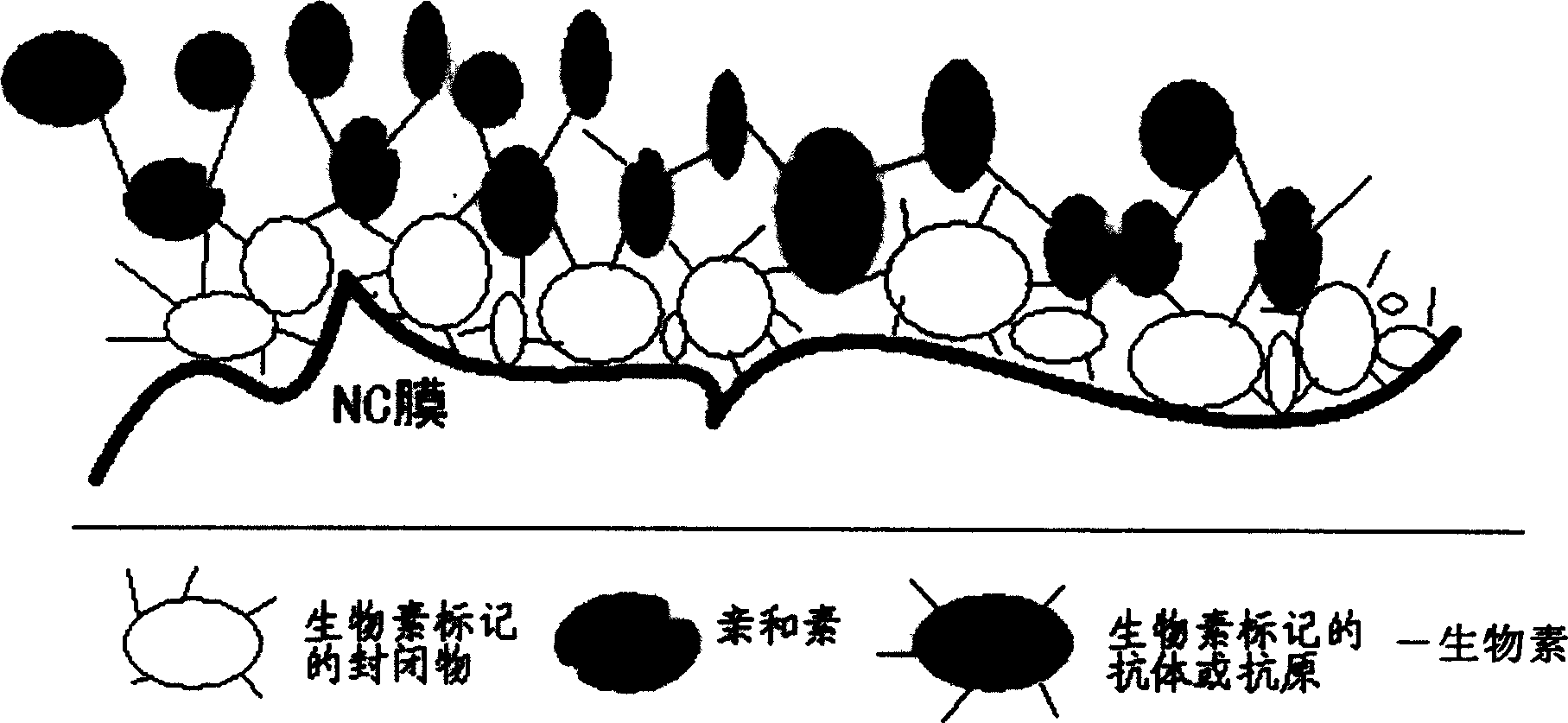
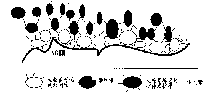
[0044] The invention also provides a preparation method of the protein chip solid phase carrier. Taking NC film as an example, its processing method includes the following steps:
[0045] (1) Pre-closed
[0046] The protein chip solid-phase carrier membrane (substrate) is pre-blocked with a biotin-labeled sealer, thereby forming a sealer layer on the solid-phase carrier.
[0047] A preferred method is to block the solid-phase carrier membrane used as a protein chip with a weight concentration of 2%-10% biotin-labeled blocker, at room temperature for 1-2 hours or overnight at 4°C.
[0048] As for soaking temperature and time, there is no particular limitation. Typically, the soaking time in the avidin-biotin complex solution is 90-150 minutes or longer at room temperature, or overnight at 4°C.
[0049] The concentration of the biotin-labeled blocker in the pre-blocking solution is usually 5-1000ug / ml, preferably 100ug / ml-500ug / ml, calculated according to the content of bioti...
Embodiment 1
[0064] Hereinafter, the detection of hepatitis C anti-HCV antibody is taken as an example to further illustrate the present invention, but it is not limited to the scope of the present invention.
[0065] (a) Preparation of protein chip solid phase carrier
[0066] Choose a hydrophilic NC membrane with a pore size of 0.4mm produced by Whatman, block with long-arm biotinylated (BCNHS) 2-10%, pH 7.8 PBS deesterified milk powder buffer, and block for 1-2 hours at room temperature or 4°C over liquid. Wash with pH 7.8 PBS buffer three times, dry at room temperature; soak in 0.5% streptavidin solution for 30 minutes, and dry in air.
[0067] (b) Preparation of protein chip
[0068] Use a high-speed spotting instrument to spot the genetically engineered fusion antigen (including Core\NS3\NS4\NS5) of hepatitis C long-arm biotinylated (BCNHS) on the above-mentioned treated NC membrane, each array 16 (4 × 4 ) samples, each with a diameter of 0.4mm, and dry at room temperature.
[00...
Embodiment 2
[0073] The sequencing of Example 1 was repeated, the only difference being that different concentrations of avidin and biotin, different ratios of avidin:biotin and different solid phase carriers were used (see Table 2 for details).
[0074] Solid phase carrier
PUM
 Abstract
Description
Claims
Application Information