
Integrated circuit

An integrated circuit, low-resistance technology, applied in the field of electromagnetically coupled integrated circuits, can solve problems such as insufficiency, and achieve the effect of reducing coupling noise

Inactive Publication Date: 2004-10-13
SHARP KK
View PDF2 Cites 6 Cited by
  • Summary
  • Abstract
  • Description
  • Claims
  • Application Information

AI Technical Summary

Problems solved by technology

In this way, the Deep N well technology is suitable for the spiral inductor and transistor structure shown in Figure 12, and the value of the coupling degree S21 between the input and output is shown in Figure 14. Although it has the effect of reducing about 5db, it is relatively compact compared to the RF LNA. is not sufficient for the application device

Method used


Image

  • Integrated circuit
  • Integrated circuit
  • Integrated circuit

Examples


Embodiment approach

[0053] When one embodiment of the present invention is described based on FIGS. 1 to 10 , it will be as follows.

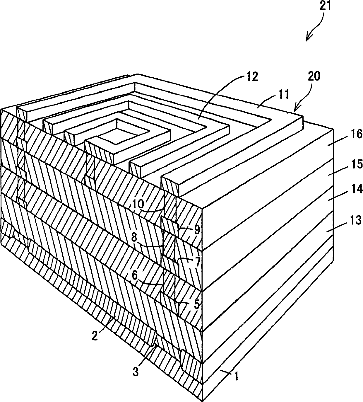
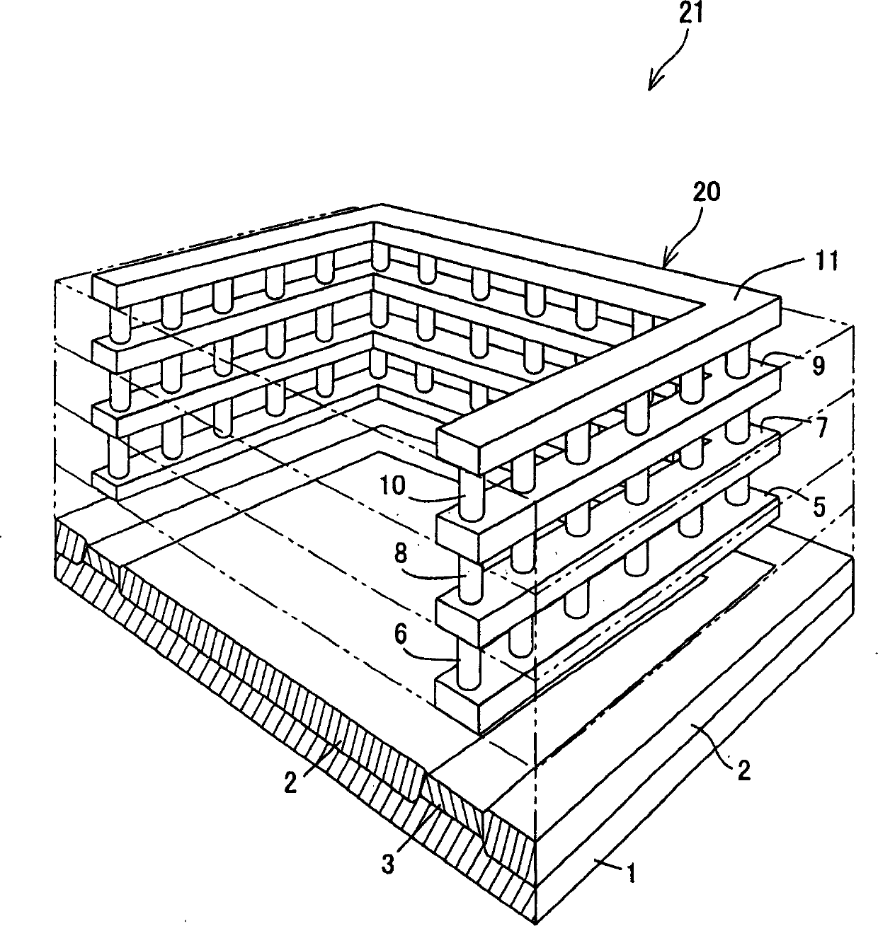
[0054] The present invention relates to electromagnetic isolation of circuit modules in integrated circuits, and in particular proposes an electromagnetic isolation structure for more effectively reducing electromagnetic coupling in the RF frequency region. Furthermore, this configuration is a valid technology for standard CMOS, BiCMOS, or bipolar processing. The configuration examples described below can prevent electromagnetic coupling and substrate crosstalk in the high-frequency region. Here, the circuit module is a high-frequency device that is an element (target element) that generates an electromagnetic field in an integrated circuit, and is a passive component such as a spiral inductor, for example.

[0055] The configuration related to the present embodiment suppresses electromagnetic coupling between circuit modules and between circuit modules and inter...


PUM


Abstract

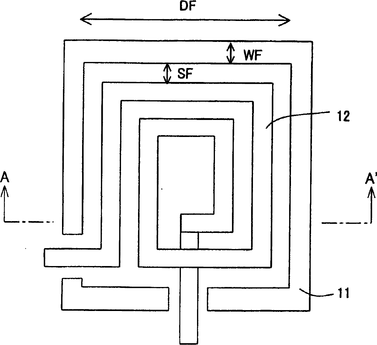
A lamination of metal wire layers forms an electromagnetic isolation structure. The metal wire layers are connected with each other by vias, so that a metal fence having a laminated structure is formed. The metal fence is provided so as to surround an element (e.g. a spiral inductor) that generates an electromagnetic field in an integrated circuit. The metal wire satisfies d‰ » / 8, WF‰¥5´, and L‰ » / 20, where ´ is a skin depth of an electromagnetic wave, c is a velocity of light, f is an operating frequency of the integrated circuit, d is a lateral-direction size of a metal-fence region, WF is a surrounding-line width of the metal fence, L is an interval between the vias, and »=c / f is a wavelength of a signal. With this arrangement, it is possible to decrease electromagnetic coupling noises and coupling noises caused via the substrate.

Description

technical field [0001] This invention relates to integrated circuits, and more particularly to integrated circuits where electromagnetic coupling at RF frequencies is a concern. Background technique [0002] A system-on-chip (SOC) is obtained by integrating multiple signals or circuits composed of digital, analog, high-frequency, etc. in one chip. Today, as shown in FIG. 11 , the interaction of these circuit blocks, especially the digital switching noise coupled on the analog circuit or the RF circuit via the silicon substrate, degrades the device characteristics. In the CMOS hybrid device design, it is known to use a deep N well to reduce the coupling of such digital switching noise to the substrate. However, when RF circuits are integrated on the same chip, interference between RF circuit modules (electrical coupling via the substrate and magnetic coupling above the substrate) affects this. The degree of RF coupling increases with the frequency used. Furthermore, in an ...

Claims


Application Information

Patent Timeline
Patent Type & Authority Applications(China)
IPC IPC(8): H01L23/52H01L21/3205H01L21/822H01L23/522H01L23/552H01L23/58H01L27/04
CPCH01L2924/0002H01L23/66H01L2924/3011H01L23/585H01L23/552H01L23/5227H01L23/645H01L2924/00A61G7/0005A61G7/02A61G7/05
Inventor A·O·阿丹
Owner SHARP KK
Learn More