Continuous casting process of monotectic alloy sheet

A thin plate and continuous casting technology, which is applied in the field of monotectic alloy thin plate continuous casting, can solve the problems of increased migration speed of dispersed phase droplets and increased size of dispersed phase droplets, so as to reduce collision condensation Effects of coarsening speed, rapid continuous solidification, and segregation reduction

Inactive Publication Date: 2004-11-24
INST OF METAL RESEARCH - CHINESE ACAD OF SCI
View PDF0 Cites 2 Cited by
  • Summary
  • Abstract
  • Description
  • Claims
  • Application Information

AI Technical Summary

Problems solved by technology

However, preliminary work shows that even under this condition, segregation along the thickness direction of the thin plate will be formed. In addition, the applicant found that when the rapid continuous solidification process of monotectic alloys was simulated, as the dispersed phase components in the alloy As the content increases, the melt temperature increases, the size of the dispersed phase droplets at the front of the solidification interface increases, and the Maragni migration velocity of the dispersed phase droplets increases

Method used


Image

  • Continuous casting process of monotectic alloy sheet
  • Continuous casting process of monotectic alloy sheet

Examples


Embodiment 1

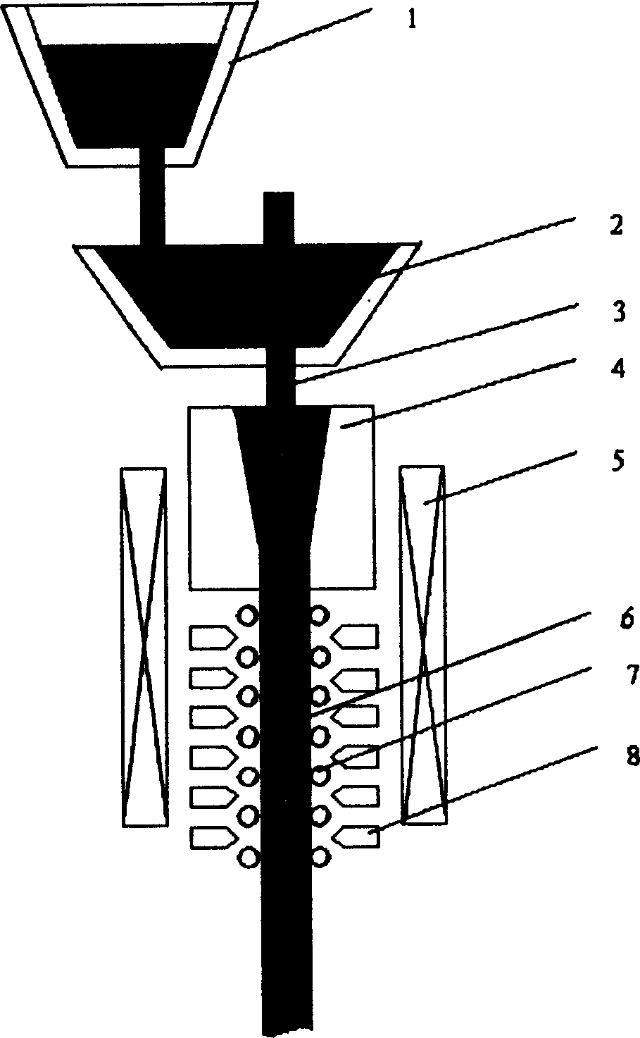
[0013] Such as figure 1 As shown, the equipment used in the present invention consists of a common thin-slab continuous casting device and a constant electromagnetic field generator 5, that is, a ladle 1, a tundish 2, a submerged nozzle 3, a crystallizer 4 (copper), and a constant electromagnetic field generator. The ladle 1 is placed above the tundish 2, the submerged nozzle 3 at the bottom of the tundish 2 is inserted into the crystallizer 4, and the cooling section 6 is below the crystallizer 4. Both sides of the cooling section 6 are provided with pressure rollers 7 in parallel, and there are cooling nozzles 8 on the outside of the pressure rollers 7. A constant electromagnetic field generator 5 is arranged parallel to the two sides of the cooling section 6 and the crystallizer 4 to form a constant electromagnetic field with a magnetic field strength of 0.4 Sla, since the electromagnetic field is located on the sides of the crystallizer 4 and the cooling section 6, it is ...

Embodiment 2

[0017] The difference from Example 1 is:

[0018] The intensity of the constant electromagnetic field is 0.5 Tesla. Under the joint action of the constant electromagnetic field and rapid solidification, a monotectic alloy sheet with uniform distribution of dispersion items is prepared.

Embodiment 3

[0020] The difference from Example 1 is:

[0021] The intensity of the constant electromagnetic field is 0.6 Tesla. Under the joint action of the constant electromagnetic field and rapid solidification, a monotectic alloy sheet with uniform distribution of dispersion items is prepared.


PUM


Abstract

The present invention relates to continuous casting technology of monotectic alloy, and is especially continuous casting process of monotectic alloy sheet. In a common continuous sheet casting apparatus, constant magnetic field of 0.3-1 tesla strength is applied to the cooling section and the crystallizing section. The constant magnetic field can increase the effective viscosity of alloy melt, retard the moving speed of dispersed phase liquid drop in liquid-liquid phase change temperature region in monotectic alloy, reduce the collision coalescence coursing speed of dispersed phase liquid drop and the separation speed of two liquid phase and decrease segregation of alloy, so that the said process of the present invention can obtain monotectic alloy with homogeneous dispersed phase particle distribution.

Description

technical field [0001] The invention belongs to the continuous casting technology of monotectic alloy, in particular to a method for continuous casting of monotectic alloy sheet. Background technique [0002] The schematic phase diagram of a monotectic alloy is shown in figure 2 shown. This type of alloy exists in the liquid state in the immiscible temperature range of components (L 1 +L 2 ). When the homogeneous alloy melt is cooled to L 1 +L 2 region, it will undergo a liquid-liquid phase transition (L→L 1 +L 2 ). This type of alloy is very extensive. If they can form a composite material in which the dispersed phase is uniformly distributed in the matrix by solidification, many of them have excellent characteristics and very important industrial applications. For example, Bi-Ga alloys have semiconductor properties, Zn-Pb alloys It is a good electrochemical material, and Al-Pb and Cu-Pb alloys are good self-lubricating materials. However, due to the metallurgical...

Claims


Application Information

Patent Timeline
Patent Type & Authority Applications(China)
IPC IPC(8): B22D11/115
Inventor 赵九洲
Owner INST OF METAL RESEARCH - CHINESE ACAD OF SCI
Why Eureka
Try Eureka