
Microwave hot forming apparatus

A technology of hot-pressing forming and microwave heating device, applied in microwave heating, presses, manufacturing tools, etc., can solve the problems of low thermal efficiency of external heat sources, uneven heating of materials, long heat conduction time, etc., to achieve automatic continuous production, Fast heating speed and uniform heating effect

Inactive Publication Date: 2004-11-24
UNIV OF ELECTRONICS SCI & TECH OF CHINA
View PDF0 Cites 9 Cited by
  • Summary
  • Abstract
  • Description
  • Claims
  • Application Information

AI Technical Summary

Problems solved by technology

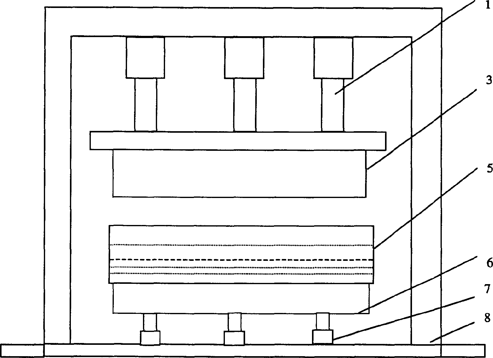
[0003] The disadvantages of traditional hot press molding equipment are: for materials with low thermal conductivity such as wood fiber, ceramics, and thermosetting (plastic) plastics, the external temperature of the material is higher than the internal temperature, and the "cold center" phenomenon often occurs. The heat conduction time is long, and the material is heated unevenly, especially for thicker materials; it is very unfavorable for the curing of the thermosetting resin in the center of the material; and the thermal efficiency of external heat sources such as oil, steam, and electric heating wires is not good. High, high energy consumption, long time, low yield

Method used


Image

  • Microwave hot forming apparatus
  • Microwave hot forming apparatus
  • Microwave hot forming apparatus

Examples


Embodiment 1

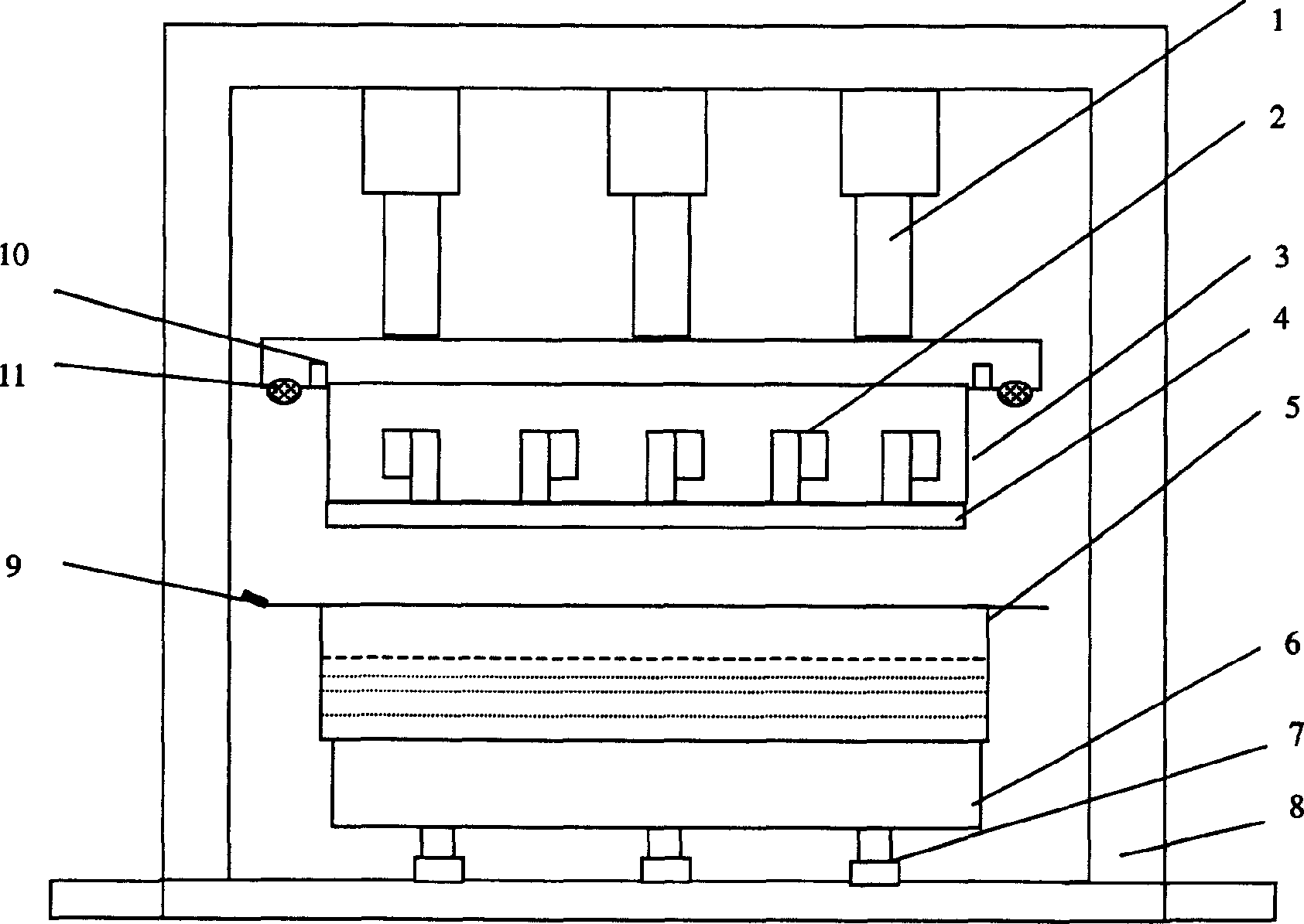
[0032] Embodiment 1: The present invention adopts the microwave energy feeding of the upper mold and the oil heating structure at the bottom of the lower mold

[0033] If the thickness of the wood fiber composite material is less than 150 mm and the area is about 6 square meters, 50 1kW / 2450MHz magnetrons can be evenly arranged in an orthogonal arrangement in the inner cavity of the upper steel mold 3, and the microwave control part consists of a The power control cabinet is under unified control. In the bottom cavity 6 of the lower mold 5, a traditional oil heating device can still be used. Microwaves act on the lower mold 5 through the energy feed port 12 on the bottom plate of the upper steel mold 3 and the microwave transparent window 4 made of quartz glass (or polytetrafluoroethylene plastic plate) with high strength and low dielectric loss of a certain thickness. The material absorbs microwaves, and its own dielectric loss heats up to achieve uniform and rapid heating a...

Embodiment 2

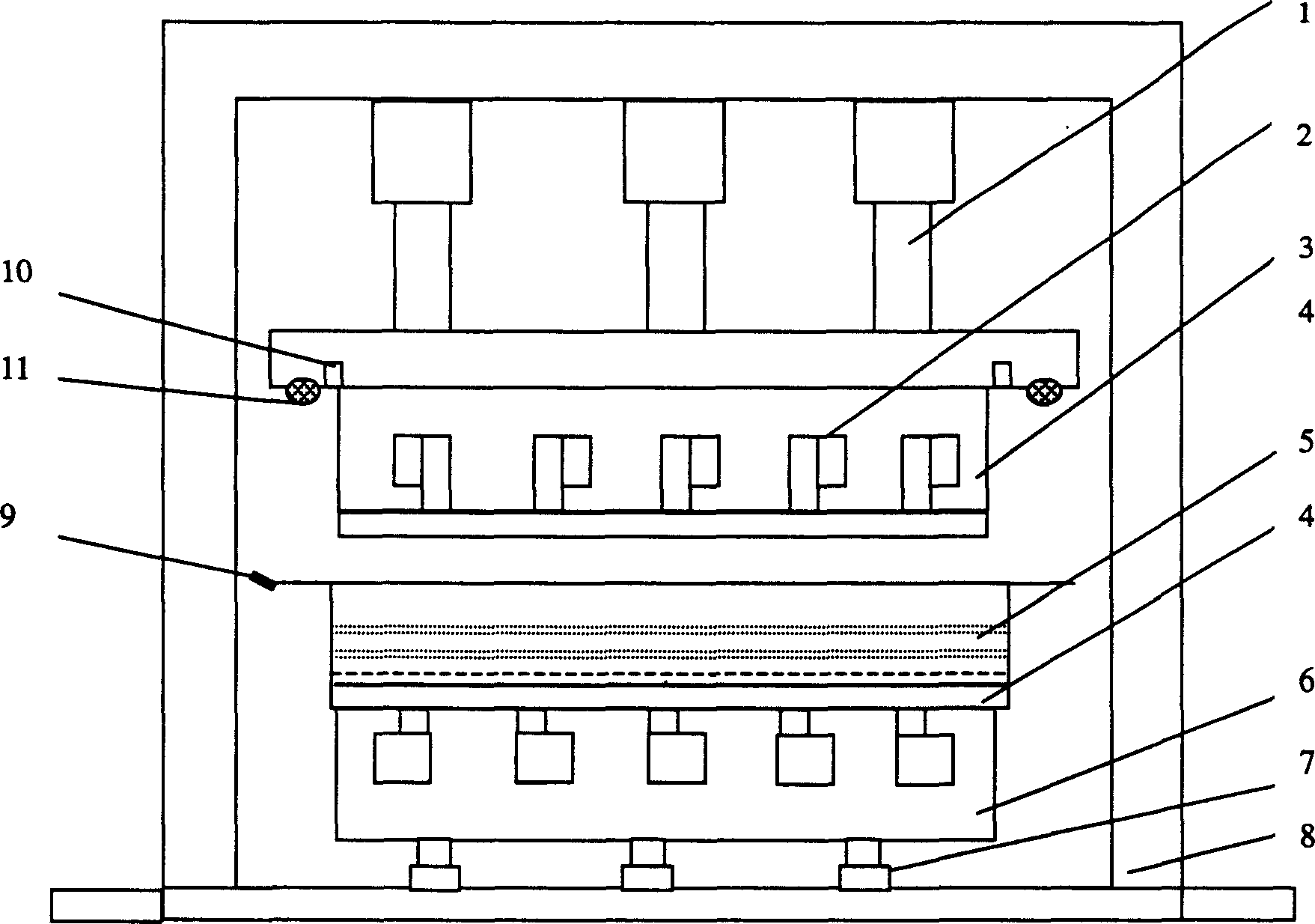
[0035] Embodiment 2: The present invention adopts the upper mold and the lower mold to set the microwave heating device structure at the same time

[0036] If the thickness of the material is more than 150 mm and less than 600 mm, and the area is about 6 square meters, 50 1kW / 2450MHz magnetron, its microwave control part is uniformly controlled by a power control cabinet. The microwave passes through the energy feed port 12 on the bottom plate of the upper steel mold 3 and the energy feed port 12 on the top plate of the bottom cavity 6 of the lower mold 5 and the quartz glass (or polytetrafluoroethylene) of high strength and low dielectric loss of a certain thickness. The microwave transparent window 4 made of plastic plate) acts on the material in the lower mold 5 up and down simultaneously, the material absorbs microwaves, and its own dielectric loss heats up so as to achieve uniform and rapid heating and curing.


PUM


Abstract

The present invention combines microwave heating technology and traditional press. The microwave hot forming apparatus includes pressing unit, microwave heater, upper and lower molds and demolding unit. The microwave heater is set inside the upper mold and / or in the bottom of the lower mold, microwave acts on the material via the energy locking port and microwave transparent window in the bottom board to heat the material via its dielectric loss. While heating, the material is microwave heated to cure and form. The present invention has the simultaneous heating of inside and outside of the material, and the heating is homogeneous, fast and high in efficiency. The present invention combines formation, curing and stoving.

Description

Technical field [0001] The invention belongs to the technical field of electromechanics, and in particular relates to the technology of heating and curing materials by using microwave energy. Background technique [0002] Traditional thermoforming equipment consists of a pressurizing device and a heating device (such as figure 1 shown). In traditional thermoforming equipment, the pressure device usually adopts a hydraulic (oil) press, which is composed of a pressure device 1, an upper steel mold 3, a lower mold 5, and a cavity 6 (at this time, in the cavity 6 oil heating device), automatic demoulding mechanism 7, frame 8, etc.; the heating device is generally filled with oil in the inner cavity of the upper steel mold 3 and the cavity 6 at the bottom of the lower mold 5, these are used The oil used to heat the material is heated by an external heat source such as an electric heating wire, and the hot oil heats the material through heat conduction, heat convection, heat rad...

Claims


Application Information

Patent Timeline
Patent Type & Authority Applications(China)
IPC IPC(8): B30B15/34H05B6/64
Inventor 谢扩军
Owner UNIV OF ELECTRONICS SCI & TECH OF CHINA
Learn More