Bicavity oil pump

An oil pumping and oil field technology, applied in the direction of pumps, pumps with flexible working elements, liquid variable capacity machines, etc., to achieve high output and avoid interlayer interference.

Inactive Publication Date: 2004-12-22
于海涛
View PDF2 Cites 6 Cited by
  • Summary
  • Abstract
  • Description
  • Claims
  • Application Information

AI Technical Summary

Problems solved by technology

The lower part of the upper outlet valve is connected to the upper part of the plunger pump barrel

Method used


Image

  • Bicavity oil pump

Examples


Embodiment Construction

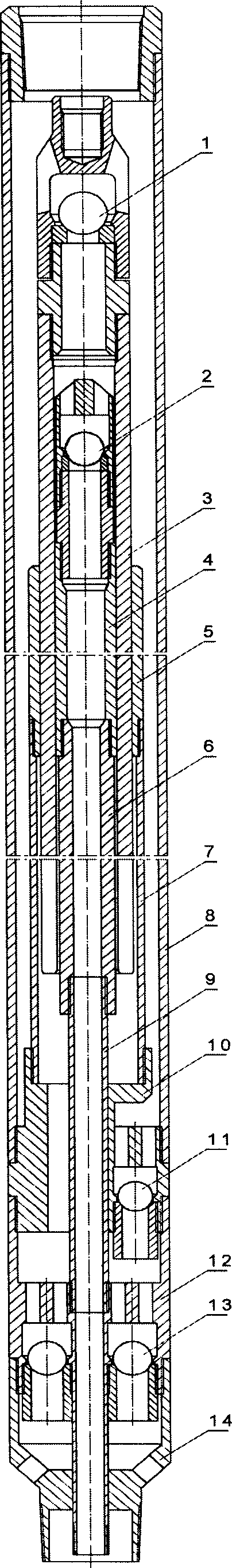
[0009] The embodiments of the present invention will be further described below in conjunction with the accompanying drawings. As shown in the figure, it consists of upper oil outlet valve 1, upper oil inlet valve 2, plunger pump barrel 3, small plunger 4, large pump barrel 5, upper connecting pipe 6, extension pipe 7, outer pipe 8, and lower connecting pipe 9 , oil outlet valve joint 10, lower oil outlet valve 11, oil inlet valve joint 12, lower oil inlet valve 13, and tail joint 14 to form. The lower part of the upper oil outlet valve 1 is connected to the upper part of the plunger pump cylinder 3 . The lower part of the large pump barrel 5 is connected to the extension pipe 7, the lower part of the upper oil inlet valve 2 is connected to the upper part of the small plunger 4, the lower part of the small plunger 4 is connected to the upper connecting pipe 6, and the plunger pump barrel 3 is located between the large pump barrel 5 and the small plunger 4 , The outer wall of ...


PUM


Abstract

Dual cavity type oil well pump is composed of upper suction valve, upper delivery valve, plunger pump barrel, small plunger, upper connecting tube, delivery valve joint, lower delivery valve, suction valve joint, and lower suction valve etc. When plunger pump barrel goes up, crude oil in one layer from lower delivery valve enters into chamber between lengthen tube and upper connecting tube, and crude oil in another layer from inlet tube connected to small screw below delivery valve joint enters into inner chamber of plunger pump barrel. When plunger pump barrel goes down, crude oil in one chamber is drained into annular space between outer tube and lengthen tube, and crude oil in another chamber is drained into upper part of delivery valve. Thus, oil in two layers is sucked respectively to make oil well reach maximum output.

Description

1. Technical field [0001] The invention relates to a double-chamber oil well pump for mechanical oil recovery in an oil field. 2. Background technology [0002] Most oil wells exploit several oil layers at the same time. Among several oil layers, some layers have high pressure, some layers have low pressure, some layers have high water content, some layers have low water content, some layers have thick oil, and some layers have thin oil. When these layers with interlayer differences are pumped by ordinary pumps, there will be interlayer interference, and some layers will not play a role, and the oil well production will be low and the water content will be high. At present, in order to avoid the occurrence of this problem, only some layers are sealed up, and only some layers are exploited, so that the oil well cannot reach the due output. 3. Contents of the invention [0003] The purpose of the present invention is to design a double-cavity oil well pump so that it can se...

Claims


Application Information

Patent Timeline
Patent Type & Authority Applications(China)
IPC IPC(8): E21B43/00F04B47/12
Inventor 高建刚唐友庆于海涛
Owner 于海涛
Why Eureka
Try Eureka