
Cannula Automatic aeration unit for air bag of intubation

An automatic inflator and self-inflating technology, applied in the field of medical devices, can solve the problems of inconvenient operation and management, tissue necrosis, massive bleeding, etc., and achieve the effect of convenient placement

Inactive Publication Date: 2005-01-05
郑兴国
View PDF0 Cites 16 Cited by
  • Summary
  • Abstract
  • Description
  • Claims
  • Application Information

AI Technical Summary

Problems solved by technology

[0005] 3. For the existing tracheal intubation, the air bag is generally deflated for 5-15 minutes every 2-3 hours to restore the blood supply to the tracheal wall tissue compressed by the air bag. It is not convenient for clinicians to operate and manage. The most important thing is: the airbag pressure is greater than 30 cm water column, which will compress the trachea wall and cause tissue ischemia (capillary microcirculation perfusion pressure is about 30 cm water column), if the pressure is between 8-30 cm water column During the period, it will also compress the venous return of the microcirculation and tissue lymphatic return, (the venous return pressure of the capillary microcirculation is about 8 cm water column), causing the stasis and edema of the compressed tissue, the blood cannot circulate, and the local compressed tissue will still be necrotic
Therefore, no matter how much pressure is used in the existing air bag inflation method, it will compress the tracheal wall, causing damage, and even necrosis, erosion, hemorrhage or perforation, which is the most common complication in the use of clinical anesthesia machines and ventilators.

Method used


Image

  • Cannula Automatic aeration unit for air bag of intubation
  • Cannula Automatic aeration unit for air bag of intubation
  • Cannula Automatic aeration unit for air bag of intubation

Examples


Embodiment 1

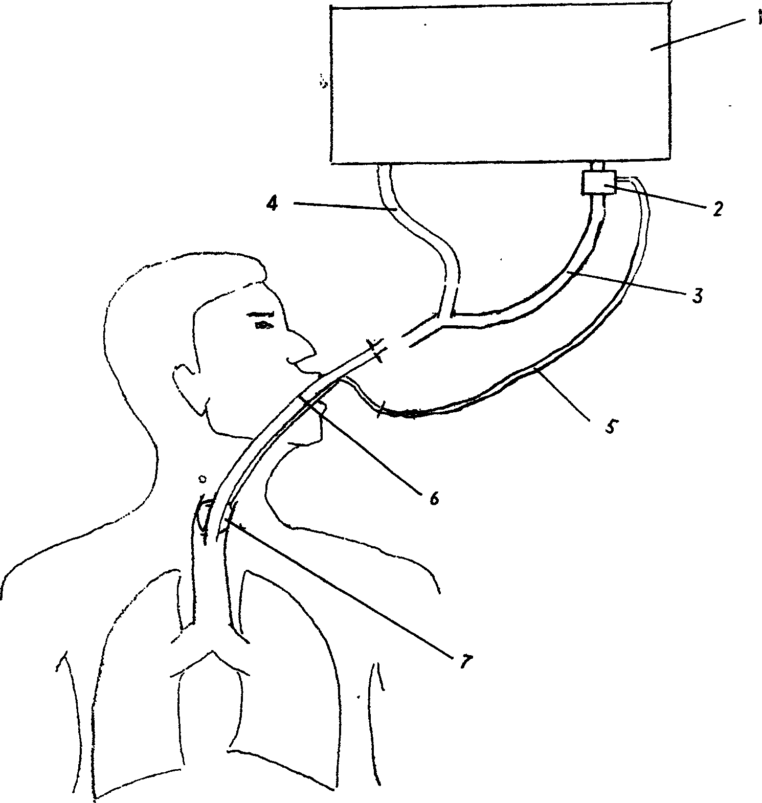
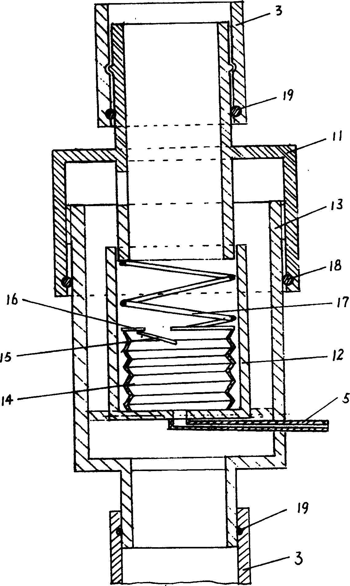
[0016] Embodiment one: if figure 2 As shown, the automatic inflation device 2 of the present invention includes an outer sleeve 11 and an inner sleeve 13, the inlet of one end of the outer sleeve 11 communicates with the upper section of the air supply pipe 3, and the other end is separately provided with an inner tube and an outer tube, wherein the inner wall of the outer tube is processed There is an internal thread, which can be screwed with the correspondingly processed external thread on the outer wall of the upper end of the inner sleeve 13 to form a connection relationship; An outlet is processed on the side of the inner tube, which communicates with the inner cavity of the inner casing 13, and communicates with the lower section of the air supply pipe 3 through the inner cavity to form an air supply channel. The inner cavity of the inner casing 13 is provided with an inner cylinder 12 communicating with the inner cavity of the inner tube of the outer casing 11. The in...

Embodiment 2

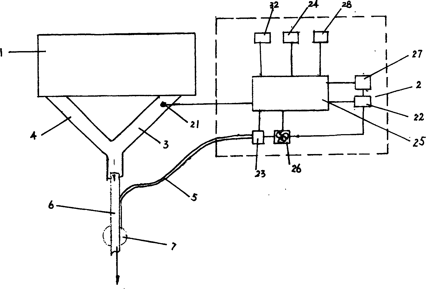
[0021] Such as image 3 As shown, the present embodiment includes a pressure sensor 21, a servo motor 22, an air pump 26 and a frequency conversion circuit 25. The pressure sensor 21 is arranged in the air supply pipe 3 and is connected to the input end of the frequency conversion circuit 25, and the output terminal of the frequency conversion circuit 25 is connected to the servo motor. 22. The air pump 26 is connected with the servo motor 22 and communicated with the balloon catheter 5 at the same time. The pressure sensor 21 can detect pressure changes in the trachea, and input different voltage signals according to the pressure. The greater the pressure, the higher the input voltage, and the pressure and voltage are linearly proportional. Described frequency conversion circuit 25 is the conventional circuit of prior art, and it can convert the signal that pressure sensor 21 measures into frequency signal, control the rotating speed of servomotor 22, the rotation of air pump...


PUM


Abstract

An automatic aerator unit for the ai bag of intubation is composed of respiratory machine, air filling tube, exhalation tube, trachea can nula, air bag, and an automatic aerator arranged on the air filling tube for automatically filling air in said air bag according to the pressure of air filling tube.

Description

Technical field: [0001] The invention belongs to the field of medical equipment, and in particular relates to an air bag automatic inflator for patient trachea intubation. Background technique: [0002] At present, the use of clinical ventilator and anesthesia machine is very extensive, involving patients with endotracheal intubation, the existing ventilator is to insert a tracheal tube into the patient's trachea, and there is an air bag at the front end of the endotracheal tube, and the inflation method of the air bag is to use The syringe manually injects 4-10ml of air from the airbag inflation tube to inflate the airbag and press the patient's tracheal wall to prevent the gas in the airway from overflowing from between the catheter and the tracheal wall. The end of the catheter is connected to the Y-shaped interface of the ventilator, so that the ventilator can The patient sends air through the trachea, so that the patient performs a passive inhalation action. When exhali...

Claims


Application Information

Patent Timeline
Patent Type & Authority Applications(China)
IPC IPC(8): A61M16/00
Inventor 郑兴国
Owner 郑兴国
Learn More