Integrated method for modification, activation, treatment delivering and spraying the absorbent

An activation treatment and absorbent technology, applied in the field of flue gas purification, can solve the problems of loss of surface activity of absorbent part, loss of porosity, and low utilization rate of absorbent, so as to reduce the probability of agglomeration and condensation and increase, appearance Irregular area and rich effect of fine cracks

Inactive Publication Date: 2005-01-05
陶国龙
View PDF1 Cites 4 Cited by
  • Summary
  • Abstract
  • Description
  • Claims
  • Application Information

AI Technical Summary

Problems solved by technology

[0004] ①The effective activity of the absorbent is low: Since the absorbent is prepared by mechanical grinding, the original micropores of the particles will be filled while the fine particles are obtained. Although the particle size of the particles becomes smaller, the outer surface area increases accordingly, but the pores The loss of the porosity reduces the porosity, which not only partially offsets the contribution of the smaller particle size to the increase of the specific surface area of ​​the absorbent to a certain extent, but also loses the surface activity of the absorbent part, and makes it difficult for the smoke to diffuse into the particles, making the inside The activity cannot be effectively exerted;
[0006] ③Absorbent activity reduction: During the use of the absorbent, not only the dynamic and continuous modification and activation treatment to improve the activity of the absorbent cannot be realized, but also the absorbent cannot be well dispersed due to too many intermediate links, resulting in coagulation. Combination, agglomeration, etc. lead to the reduction of the original activity;
[0007] ④Low ut

Method used


Image

  • Integrated method for modification, activation, treatment delivering and spraying the absorbent
  • Integrated method for modification, activation, treatment delivering and spraying the absorbent
  • Integrated method for modification, activation, treatment delivering and spraying the absorbent

Examples


Embodiment 1

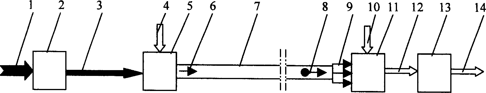
[0071] Such as figure 1 As shown, one or two or more original absorbents 1 used for the removal of sulfur oxides / nitrogen oxides in flue gas are adjusted to the absorbent to be treated by the metering mechanism 2 according to the required speed (speed adjustable) 3 supply the jet milling device 5, and the jet milling device 5 can select jet mills with different processing capacities on the market according to needs. Under the action of water vapor with a temperature of 250-350°C and an absolute pressure of 0.9-1.3 MPa as the pulverizing airflow 4, the absorbent 3 to be treated is accelerated in the jet pulverization device 5 and collides with each other or with each other at a very high relative speed. The target area is impacted and broken into finer particles, producing abundant micro-cracks, exposing the fresh surface, and mixing and adhering to each other at the same time, so that it becomes the modified and activated absorbent 6. form a gas-solid two-phase flow with the ...

Embodiment 2

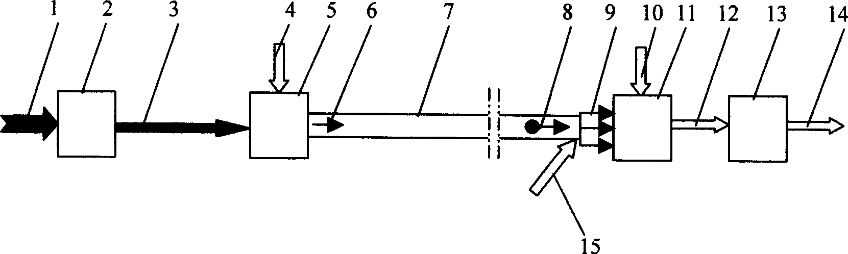
[0073] Such as figure 2 As shown, on the basis of Example 1, the injection booster gas 15 is provided at the nozzle 9, so that the absorbent 8 after further modification and activation can obtain a higher injection velocity, so as to meet the needs of a larger space in the flue gas channel 10. Requirements for the cross-section to be mixed with flue gas.

Embodiment 3

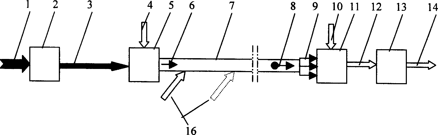
[0075] Such as image 3 As shown, on the basis of Embodiment 1, one or more places along the pneumatic conveying pipeline 7 are provided with conveying booster gas 16 to make up for the pulverized airflow 4 after the completion of the crushing treatment of the absorbent 3 to be treated. The remaining pressure cannot meet the insufficient delivery distance or injection speed requirements.


PUM

PropertyMeasurementUnit
Particle sizeaaaaaaaaaa

Abstract

An integrated method for modifying, activating, delivering and spraying the absorbent includes such steps as introducing raw absorbent in airflow breaking, breaking and cracking the absorbent to increase its specific surface area and porosity while mixing its particles, pneumatically delivering it, and directly spraying it to the fume to be treated.

Description

technical field [0001] The invention relates to a flue gas purification technology, in particular to an integrated method of absorbent modification, activation, treatment, transportation and injection, which is suitable for the technical field of removing sulfur oxides / nitrogen oxides in flue gas. Background technique [0002] Whether in power plants or in other industries, the sulfides and nitrogen oxides contained in the flue gas produced by boilers burning coal are one of the main sources of air pollution. As the problem of environmental pollution becomes more and more serious, people pay more and more attention to environmental governance and environmental protection, and have formulated strict flue gas emission standards. A variety of boiler flue gas purification treatment technologies have emerged to remove the pollutants in the flue gas. Sulfides and nitrogen oxides. The use of absorbents for dry flue gas desulfurization / denitrification is one of the main methods of ...

Claims


Application Information

Patent Timeline
IPC IPC(8): B01D53/81
Inventor 陶国龙
Owner 陶国龙
Why Eureka
Try Eureka