Process for preparing hydrogen by catalytic partial oxidation of liquid hydrocarbon

A technology for the catalytic part of alkane and liquid hydrocarbons, applied in chemical instruments and methods, hydrogen, inorganic chemistry, etc., can solve the problems of low yield of target product hydrogen, high operating temperature, high catalyst cost, etc., and achieve high activity of reaction catalysts , high hydrogen yield and low catalyst cost

Inactive Publication Date: 2005-01-26
DALIAN INST OF CHEM PHYSICS CHINESE ACAD OF SCI
View PDF1 Cites 0 Cited by
  • Summary
  • Abstract
  • Description
  • Claims
  • Application Information

AI Technical Summary

Problems solved by technology

In the above process, the O / C ratio is also high, and the operating temperature is high at the same time. Due to the use of noble metal catalysts, the cost of the catalyst is high, but the yield of the target product hydrogen is not very high.

Method used


Image

  • Process for preparing hydrogen by catalytic partial oxidation of liquid hydrocarbon
  • Process for preparing hydrogen by catalytic partial oxidation of liquid hydrocarbon
  • Process for preparing hydrogen by catalytic partial oxidation of liquid hydrocarbon

Examples


Embodiment 1

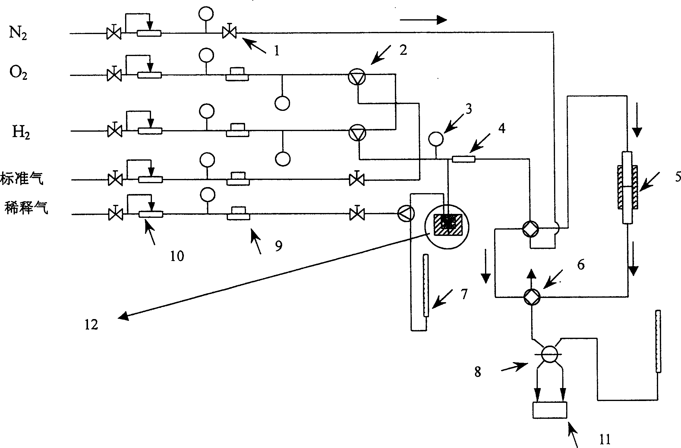
[0028] The reaction main device process structure that the present embodiment adopts is as follows figure 1 As shown, it is mainly composed of flow control equipment, mixer 4, reactor 5, chromatograph 11 as detection equipment and liquid hydrocarbon raw material feeding device 12. The reaction pipeline is a stainless steel pipe, and the liquid hydrocarbon and mixer 4 and reactor 5 The stainless steel pipeline between them is wound with a heating tape, which is heated during the reaction to prevent the condensation of liquid hydrocarbons in the pipeline. Wherein: the flow control equipment includes a stop valve 1, a three-way valve 2, a precision pressure gauge 3, a four-way valve 6, a flow meter 7, a six-way valve 8, a mass flow meter 9, and a steady flow valve 10.

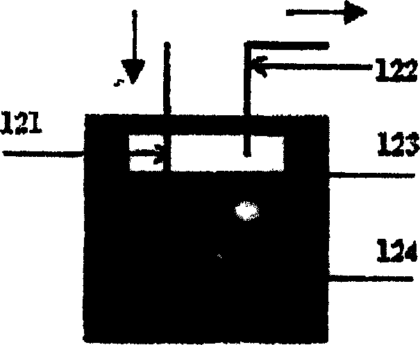
[0029] diagram 2-1 It is a schematic diagram of the structure of the feeding device for liquid hydrocarbons. The liquid hydrocarbon feedstock is placed in an airtight glass container 124, and then placed in a co...

Embodiment 2

[0037] The difference from Example 1 is:

[0038] Adopt the Ni / Al prepared by embodiment 1 2 o 3 As a reaction catalyst, the partial oxidation reaction was carried out under the conditions of O / C of 1.03, 1.1, 1.3, 1.5, and 1.7, respectively. The hydrogen selectivity in the reaction varies with temperature as Figure 4 shown. When O / C=1.7, the hydrogen production rate is 68%, and when O / C=1.03, the hydrogen production rate can reach 95%.

Embodiment 3

[0040] 1) Preparation of Ni / Al with a loading of 5-10wt% 2 o 3 catalyst.

[0041] 10g Al 2 o 3 0.4M Ni(NO 3 ) 2 20 ml of the solution was dried at 100° C. and calcined at 850° C. for 4 hours to obtain the desired catalyst. The Ni loading of the active component was about 5 wt%.

[0042] 10g Al 2 o 3 0.5M Ni(NO 3 ) 2 20 ml of the solution was dried at 100° C. and calcined at 850° C. for 4 hours to obtain the desired catalyst. The Ni loading of the active component was about 7 wt%.

[0043] 10g Al 2 o 3 0.8M Ni(NO 3 ) 2 20 ml of the solution was dried at 100° C. and calcined at 850° C. for 4 hours to obtain the desired catalyst. The Ni loading of the active component was about 10 wt%.

[0044] 2) Partial oxidation hydrogen production reaction

[0045] The loadings prepared in this example are 5wt%, 7wt%, 10wt% Ni / Al 2 o 3 catalyst, at a space velocity of 1.0 x 10 4 l / kg / h, 1.8×10 4 l / kg / h, 2.8×10 4 l / kg / h, 850°C, O / C=1.08, He / C 7 h 16 Under the condition of...


PUM

PropertyMeasurementUnit
specific surface areaaaaaaaaaaa

Abstract

The invention discloses a process for preparing hydrogen by catalytic partial oxidation of liquid hydrocarbon using nickel based and/or noble metal as supported catalyst of the active component, controlling the reaction temperature between 750-900 deg. C, airspeed between 1.0X10#+[3] l/kg/hí½12.5X10#+[5] l/kg/h, using oxygen as oxidation agent for partial oxidation reaction for the liquid hydrocarbons, wherein inert diluted gas can be added, the mol ratio of the inert diluted gas and liquid hydrocarbons is between 0-15.

Description

technical field [0001] The invention relates to liquid hydrocarbon catalytic conversion production technology, in particular to a liquid hydrocarbon catalytic partial oxidation hydrogen production method. Background technique [0002] Hydrogen is a very important chemical raw material. It plays an important role in the refining of gasoline and the synthesis of other chemical and chemical products. At the same time, hydrogen is also an efficient and clean energy source. Some experts predict that hydrogen energy will play a dominant role in the energy structure in the middle of the 21st century for the rational and efficient use of existing fossil energy and the sustainable development of mankind. [0003] A fuel cell is a power generation device that directly converts chemical energy stored in fuel and oxidant into electrical energy through electrode reactions, with high energy conversion efficiency and low environmental pollution. In the 1990s, proton exchange membrane fu...

Claims


Application Information

Patent Timeline
Patent Type & Authority Applications(China)
IPC IPC(8): C01B3/34C01B3/36C01B3/40
Inventor 冉然熊国兴杨维慎
Owner DALIAN INST OF CHEM PHYSICS CHINESE ACAD OF SCI
Why Eureka
Try Eureka