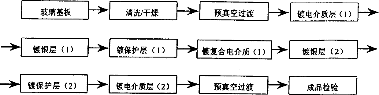
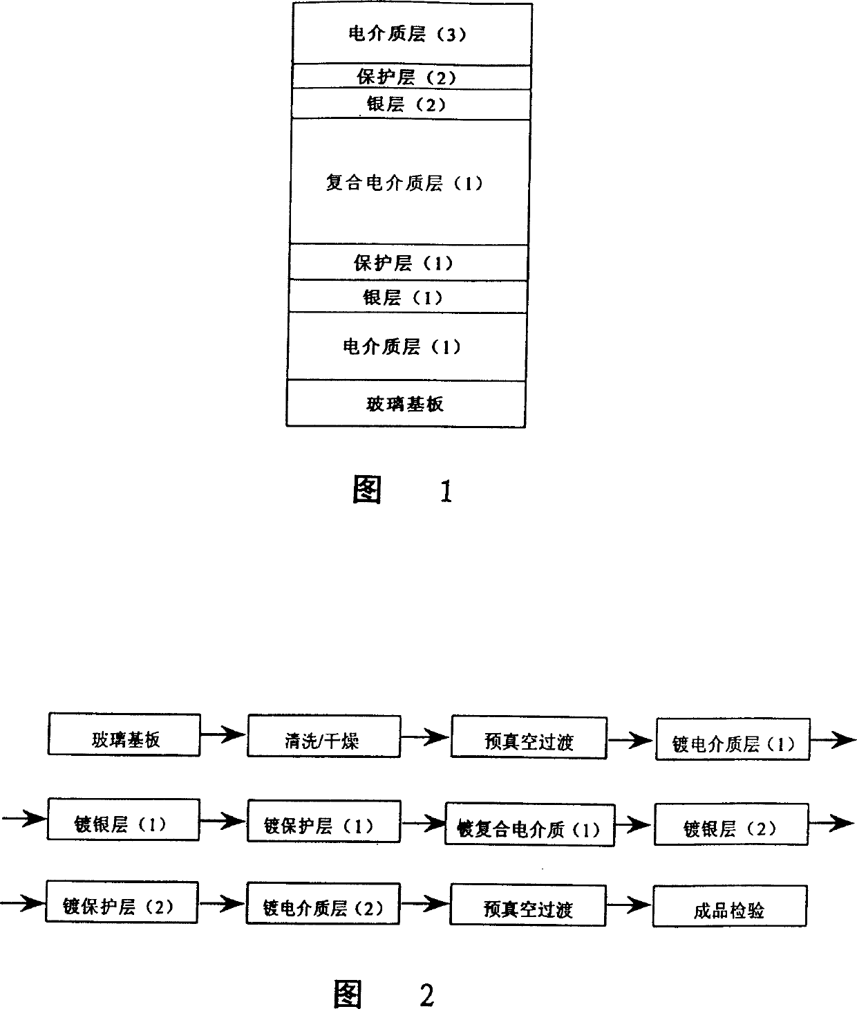
Double silver low-emissivity coated glass based on composite dielectric layer
A low-emissivity coating and dielectric layer technology, applied in sputtering, coating, ion implantation, etc., can solve the problem of uncoated glass, etc., to achieve improved sunshade performance, high transmittance, radiation rate reduction effect
- Summary
- Abstract
- Description
- Claims
- Application Information
AI Technical Summary
Problems solved by technology
Method used
Image

Examples
Embodiment Construction
[0022] The flat glass double-end continuous coating machine used in the present invention includes 11 AC cathodes and 10 DC cathodes, adopts the process parameters listed in the following table, uses 6 AC double targets, and 4 DC single targets, with a total of 10 target positions Carry out production, make double-silver low-emissivity glass of the present invention, its process parameter and the position list of target are as follows:
[0023] Target
serial number
Types of
target material
sputtering process
barometric pressure
(hPa)
process gas
Element
film layer
thickness
(nm)
1#
AC double target
3.95×10 -3
=45:55
17
2#
AC double target
3.25×10 -3
=45:55
18
3#
...
PUM
| Property | Measurement | Unit |
|---|---|---|
| refractive index | aaaaa | aaaaa |
| reflectance | aaaaa | aaaaa |
Abstract
Description
Claims
Application Information
 - R&D
- Intellectual Property
- Life Sciences
- Materials
- Tech Scout
- Unparalleled Data Quality
- Higher Quality Content
- 60% Fewer Hallucinations
Browse by: Latest US Patents, China's latest patents, Technical Efficacy Thesaurus, Application Domain, Technology Topic, Popular Technical Reports.
© 2025 PatSnap. All rights reserved.Legal|Privacy policy|Modern Slavery Act Transparency Statement|Sitemap|About US| Contact US: help@patsnap.com