Motionless electromagnetic generator

An electromagnetic generator, magnetic circuit technology, applied in the direction of transformer/inductor core, circuit, inductor, etc., can solve problems such as reducing generator efficiency

Inactive Publication Date: 2005-02-16
斯蒂芬·L·帕特里克 +4
View PDF10 Cites 6 Cited by
  • Summary
  • Abstract
  • Description
  • Claims
  • Application Information

AI Technical Summary

Problems solved by technology

In most traditional applications of permanent magnet generators, a magnetic field is generated in the coil by applying voltage to the coil, and this magnetic field is used as a magnetic field over the permanent magnet, so in order to provide power to the switching device, it is necessary to power the generator machine provides a large amount of energy, reducing the efficiency of the generator

Method used


Image

  • Motionless electromagnetic generator
  • Motionless electromagnetic generator
  • Motionless electromagnetic generator

Examples


Embodiment Construction

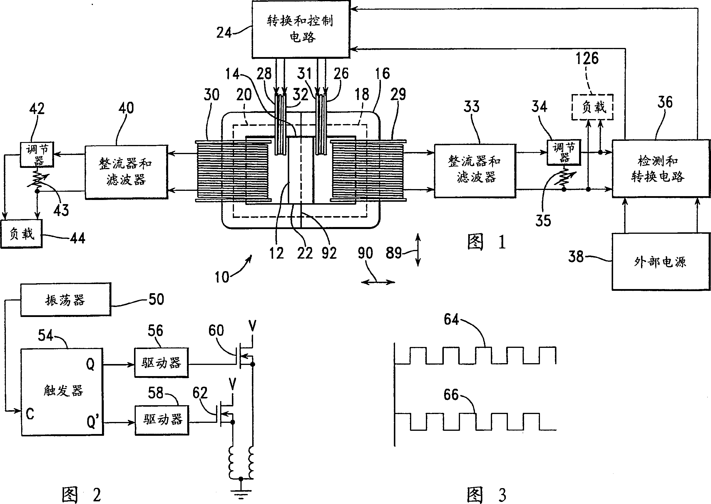
[0042] 1 is a partially schematic front view of an electromagnetic generator 10 manufactured in accordance with a first embodiment of the invention, including a permanent magnet 12 to provide for flow outward from the N pole 14 of the permanent magnet 12 into a magnetic core material 16. The input line of the magnetic flux. The flux core material 16 is assembled to form a right magnetic circuit 18 and a left magnetic circuit 20 that extend outwardly between the N pole 14 and the S pole 22 of the magnet 12 . The electromagnetic generator 10 is driven by a switching and control circuit 24 that alternately drives current through a right input coil 26 and a left input coil 28 . Each of these input coils 26 , 28 extends around a portion of the core material 16 such that the right input coil 26 surrounds a portion of the right magnetic circuit 18 and the left input coil 28 surrounds a portion of the left magnetic circuit 20 . The right output coil 29 also surrounds a portion of the...


PUM

PropertyMeasurementUnit
thicknessaaaaaaaaaa

Abstract

An electromagnetic generator without moving parts includes a permanent magnet and a magnetic core including first and second magnetic paths. A first input coil and a first output coil extend around portions of the first magnetic path, while a second input coil and a second output coil extend around portions of the second magnetic path. The input coil are alternatively pulsed to provide induced current pulses in the second output coil. Driving electrical current through each of the input coils reduces a level of flux from the permanent magnet within the magnetic path around which the input coil extends.

Description

technical field [0001] This invention relates to magneto generators which can be used to generate electricity without moving parts, and more particularly to such a device which has the capability of generating electricity without externally inputting electrical energy through input coils in operation. [0002] This application claims priority to co-pending US Application Serial No. 09 / 656,313, filed September 6,2000. Background technique [0003] This patent document describes several magneto generators, each magneto comprising a permanent magnet, two magnetic circuits outside the permanent magnet, each magnetic circuit extending between opposite poles of the permanent magnet, for making the magnetic flux A switching device passing alternately between either of the two magnetic circuits, and one or more output coils in which currents are induced to flow by means of changes in the magnetic field in the device. These devices operate according to a generalization of Faraday's ...

Claims


Application Information

Patent Timeline
Patent Type & Authority Applications(China)
IPC IPC(8): H01F3/10H01F27/24H01F27/28H01F29/14H02K53/00H02M3/28H02M3/325
CPCH01F3/10H01F29/146H02K53/00H01F29/14B82Y40/00
Inventor 斯蒂芬·P·帕特里克托马斯·E·比尔登詹姆斯·C·海斯肯尼思·D·穆尔詹姆斯·L·肯尼
Owner 斯蒂芬·L·帕特里克
Why Eureka
Try Eureka