Apparatus for recycling and supplying lubricating oil

A lubricating oil and equipment technology, applied in the field of lubricating oil circulation supply equipment, can solve the problems of shortening the life of the catapult, increasing the waste of lubricating oil, increasing the manufacturing cost, etc.

Inactive Publication Date: 2005-02-23
朴昌福
View PDF0 Cites 3 Cited by
  • Summary
  • Abstract
  • Description
  • Claims
  • Application Information

AI Technical Summary

Problems solved by technology

The lubricating oil supplied to the drive unit of the catapult is collected in a collection bucket installed separately from the catapult so that the lubricating oil cannot be recycled
This increases wastage of lubricating oil, which increases manufacturing costs
[0003] In addition, since the lubricating oil in the catapult cannot be recycled, the staff should continuously supply the lubricating oil to the lubricating oil supply device, which will reduce the work efficiency
In addition, if the operator makes a mistake and does not supply enough lubricating oil, it will damage the drive unit of the catapult, thereby shortening the life of the catapult
[0004] Also, since the lubricating oil collection cylinder in conventional catapults is installed independently, the continuous release of lubricating oil from the catapult will cause environmental pollution

Method used


Image

  • Apparatus for recycling and supplying lubricating oil
  • Apparatus for recycling and supplying lubricating oil
  • Apparatus for recycling and supplying lubricating oil

Examples


Embodiment Construction

[0020] Preferred embodiments of the lubricating oil circulation supply device according to the present invention and related technologies will be described in detail below with reference to the accompanying drawings.

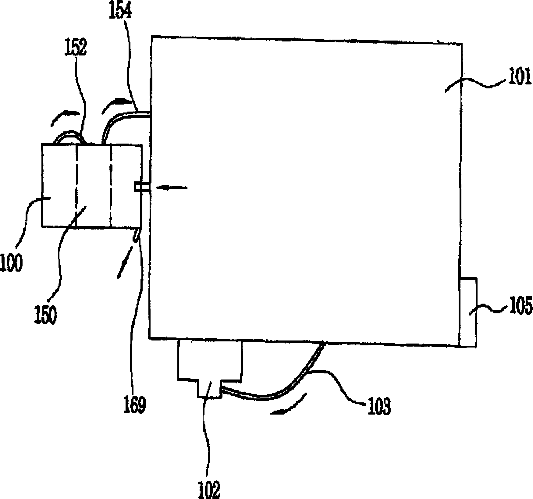
[0021] figure 1 is a block diagram illustrating the structure of lubricating oil circulation supply equipment in the present invention. exist figure 1 Among them, the reference numeral 101 represents a common catapult, the reference numeral 105 represents a common control panel for controlling the catapult 101, and the reference numeral 102 represents a commonly used solenoid valve, which is used to output a control signal through the oil pressure so as to control the catapult 101. installed drive unit. The present invention also provides a lubricating oil circulation supply device 100 , which is connected to the side of the catapult 101 through a second supply conduit 154 for filtering the lubricating oil from the catapult 101 and then supplying the lubricati...


PUM


Abstract

An apparatus for recycling and supplying lubricating oil which filters lubricant discharged from a catapult device and separates water contained in the lubricant for repeated usage has a storage device (180) which includes a first chamber (122) in which lubricant discharged from a catapult device (10) is flowed, a second filtering member (126) for filtering the lubricant in the first chamber (122), a water separating unit (160) for separating water from the lubricant filtered in the filtering member (126), a third chamber (132) for storing lubricant filtered in a third filtering member (134), a fourth filtering member (136) for filtering the lubricant in the third chamber (132) again, a fourth chamber (134) for filtering the lubricant filtered in the fourth filtering member (136), a motor pump (150) for supplying the lubricant filtered in the fourth chamber (134) to a driving unit of the catapult device (101), and a central chamber (140) for mounting the motor pump (150).

Description

technical field [0001] The present invention relates to a lubricating oil circulating supply device, and more particularly, to a lubricating oil circulating supply device which filters the lubricating oil from the catapult and then separates the moisture in the lubricating oil so that the lubricating oil can be reused use. Background technique [0002] A conventional lubricating oil supply device is connected to the catapult to periodically supply lubricating oil to the drive unit in the catapult. The lubricating oil supplied to the drive unit of the catapult is collected in a collection bucket installed separately from the catapult, so the lubricating oil cannot be recycled. This increases wastage of lubricating oil, thereby increasing manufacturing costs. [0003] In addition, since the lubricating oil in the catapult cannot be recycled, the staff should continuously supply the lubricating oil to the lubricating oil supply device, which will reduce the working efficiency...

Claims


Application Information

Patent Timeline
Patent Type & Authority Applications(China)
IPC IPC(8): B01D17/02B01D36/00C10M175/00F16N39/00F16N39/06
CPCC10M175/0058B01D17/0208B01D36/003F16N39/06F16N39/00B01D17/0214B01D17/10
Inventor 李熙敦
Owner 朴昌福
Why Eureka
Try Eureka