
Failure current limiter

A fault current and limiter technology, applied in electrical components, circuit devices, emergency protection circuit devices for limiting overcurrent/overvoltage, etc. Problems such as failure to work normally, to achieve the effect of limiting fault current, improving utilization efficiency and reducing cost

Inactive Publication Date: 2005-03-02
TSINGHUA UNIV
View PDF0 Cites 2 Cited by
  • Summary
  • Abstract
  • Description
  • Claims
  • Application Information

AI Technical Summary

Problems solved by technology

This requires more complex and reliable GT0 drive and synchronous control technology, otherwise the device will not work properly
[0004] (2) The on-state loss of GTO is large
[0005] At present, the above two problems have not been well resolved, thus limiting the application of fault current limiters with this structure

Method used


Image

  • Failure current limiter
  • Failure current limiter
  • Failure current limiter

Examples


Embodiment Construction

[0019] The fault current limiter proposed by the present invention is described in detail as follows in conjunction with the accompanying drawings and embodiments:

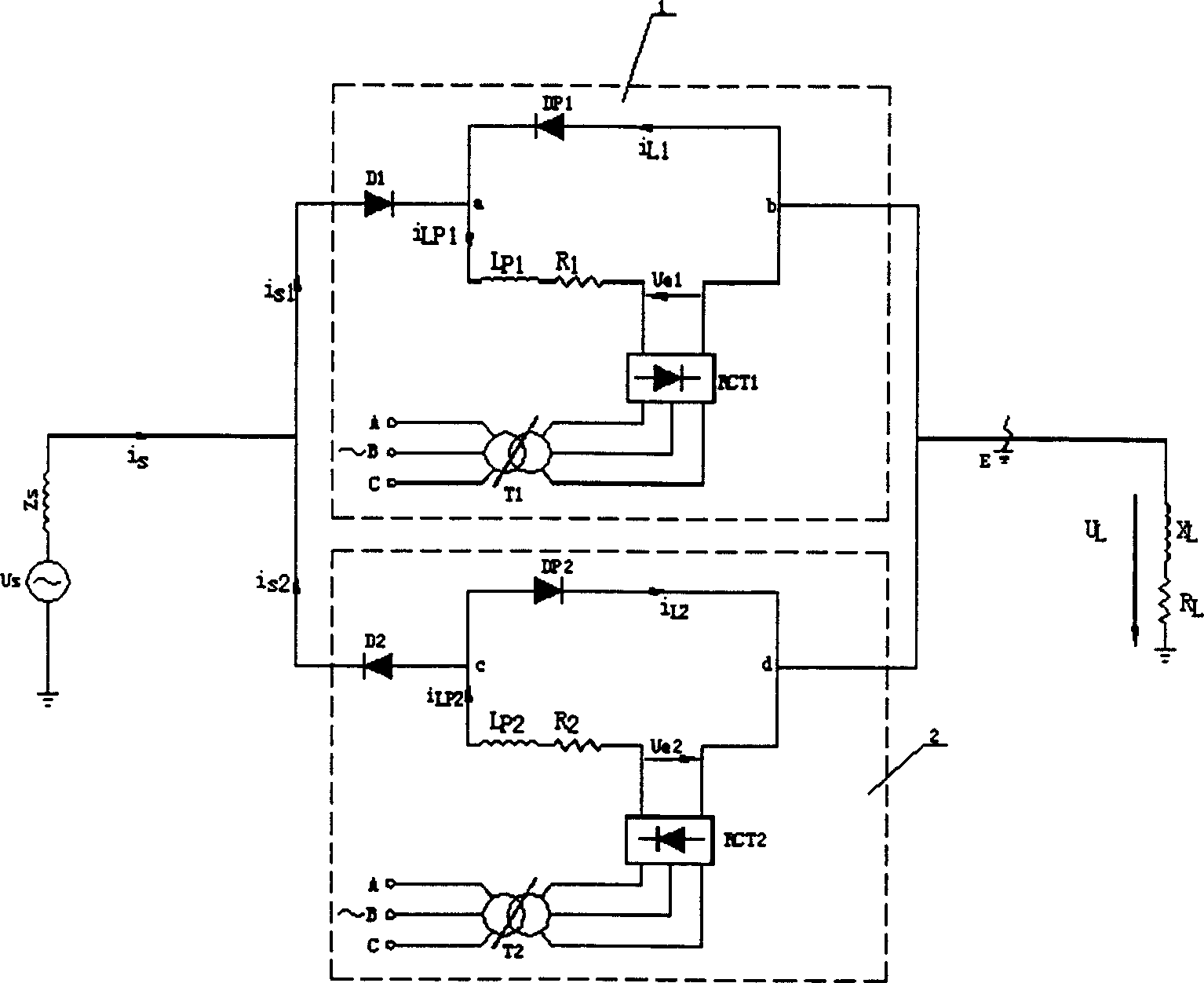
[0020] The circuit of the present invention such as figure 2 As shown, among them, 1 is the current limiting unit working in the positive half cycle of the grid voltage, and 2 is the current limiting unit working in the negative half cycle of the grid voltage; wherein, the current limiting unit working in the positive half cycle of the grid voltage includes: two working in Fast recovery diodes D1 and DP1 for the positive half cycle of the grid voltage; a current-limiting inductor LP1 and a current-limiting resistor R1; a three-phase uncontrolled rectifier bridge RCT1 providing DC bias current for the current-limiting circuit, and a three-phase uncontrolled rectifier The bridge provides the AC input voltage regulating transformer T1; wherein the fast recovery diode DP1, the current limiting inductor LP1, the curre...


PUM


Abstract

This invented fault current limiter comprises: two current-limting units working for positive half-period and negative half-period of power network voltage, which two having respectively two recovery diodes, a current-limiting inductance, a current-limiting ersistance, a three-phase non wave rectifier to apply dc bias current to limiting-circuit and a regulating transformer to apply ac niput to three phase non wave rectifier. In this invention, according different load, by regulating branch termnial of regulating transformer by vary output voltage of non wave rectifier, so varying dc bias current in limiting circuit, the normal working current passes no current-limiting inductance and resistance, while fault of short circuit, the current passes current-limitnig inductance and resistance, so, limiting current of short-circuit. Advantages are: lost cost diode being substituted for expensive controllable electric power electronic device, so lowering the cost of said product.

Description

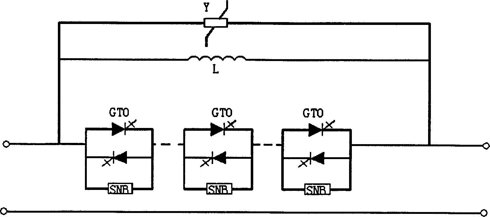
technical field [0001] The invention belongs to the technical field of power equipment, and in particular relates to a fault current limiter without using controllable power electronic devices. Background technique [0002] A fault current limiter is a device used to limit fault current. Currently more practical fault current limiter such as figure 1 As shown, it mainly consists of three parts: a fast-acting GTO switch (including the snubbing circuit SNB of the GTO switch), a current-limiting impedance L, a zinc oxide arrester Y, and a set of current detection devices and a set of control device (not shown in the figure). The GTO switch is driven by the rising rate of the current, and can be turned into an off state within tens of microseconds, and can break a large current. When working normally, the GTO switch is in a fully conductive state; when a fault occurs, the GTO is disconnected quickly, and the fault current flows through the current-limiting impedance. termina...

Claims


Application Information

Patent Timeline
Patent Type & Authority Applications(China)
IPC IPC(8): H02H9/02
Inventor 姜齐荣黄玮
Owner TSINGHUA UNIV
Learn More