Method and device for polishing the surface of a gas turbine blade

A technology of gas turbine blades and ceramics, which is applied in the field of gas turbine blades, and can solve the problems of burr formation, troublesome manual guidance, contamination of impurities, etc.

Inactive Publication Date: 2005-03-23
SIEMENS AG
View PDF11 Cites 11 Cited by
  • Summary
  • Abstract
  • Description
  • Claims
  • Application Information

AI Technical Summary

Problems solved by technology

Drilling holes with a laser beam has advantages in terms of time and costs, but often results in the formation of burrs and contamination of welded or remelted particles due to the action of heat
These burrs had to be removed in order to maintain the exact geometry of the film cooling holes, which hitherto required cumbersome manual-guided work

Method used


Image

  • Method and device for polishing the surface of a gas turbine blade
  • Method and device for polishing the surface of a gas turbine blade
  • Method and device for polishing the surface of a gas turbine blade

Examples


Embodiment Construction

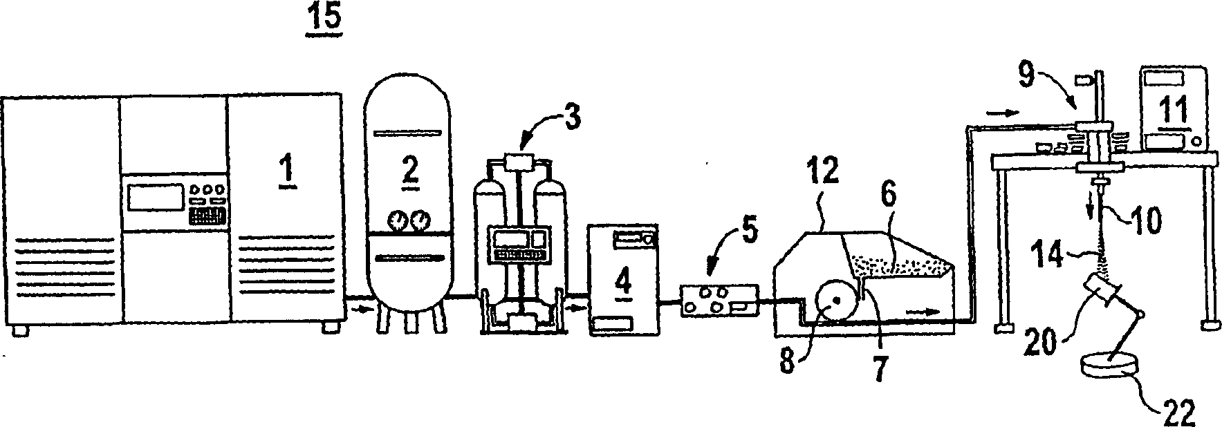
[0031] figure 1An apparatus 15 for removing ceramic material from the surface of a gas turbine blade 20 is shown. In order to generate the compressed air flow, a screw compressor 1 , an equalization tank 2 , an adsorption dryer 3 , a cooler 4 and a measuring system 5 are connected in series. In the screw compressor 1 the air is highly compressed, in particular to a pressure of 3 to 12 bar. Balance tank 2 is used to stabilize a constant mass flow. The air is dried in the adsorption dryer 3 and cooled in the cooler 4 . The measuring system 5 is used to detect compressed air parameters.

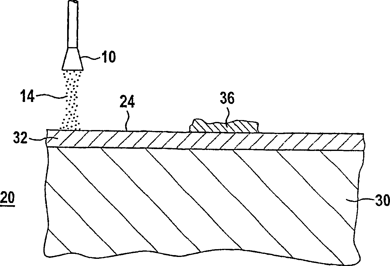
[0032] The compressed gas flow is then fed into a pellet supply device 12 . Dry ice pellets 6 are stored in the pellet supply device 2 . The dry ice pellets 6 are fed by means of a screw conveyor 7 via an impeller lock 8 into the compressed air flow and together with the compressed air flow are supplied to a Rafal nozzle 10 which is moved by a robot 9 . There they are discharged as dry ice...


PUM


Abstract

The invention relates to a method and device for polishing the surface (24) of a gas turbine blade (20). According to the invention, a metallic anticorrosive layer (32) is polished by using a stream of dry ice (14) whereby preventing the surface (24) from becoming contaminated and obtaining cost advantages.

Description

technical field [0001] The invention belongs to the field of gas turbine blades, and relates to coating or repairing a protective layer or a protective layer system on the gas turbine blades. Background technique [0002] For example US 4321310, US 4676994 or US 5238752 disclose some protective coating systems on gas turbine blades. Gas turbine blades are subjected to very high temperatures. In order to have the necessary high-temperature strength, they are made of high-temperature-resistant materials. In particular nickel- or cobalt-based superalloys are considered. Usually, a protective layer or a protective layer system is also applied to the base body of such gas turbine blades for protection against oxidation, corrosion and / or for thermal insulation. Particularly suitable here are metal alloys of the type MCrAlY, in which M is an element of the group (Fe, Co, Ni), Cr is chromium, Al is aluminum, and Y is yttrium or a rare earth element. Such an anti-corrosion layer ...

Claims


Application Information

Patent Timeline
Patent Type & Authority Applications(China)
IPC IPC(8): B23P6/00B24C1/00B24C1/08
CPCB24C1/003B24C1/083B23P2700/06B24C1/08B24C1/086
Inventor 博里斯·巴布拉思费利克斯·埃尔宾马克·克里格格哈德·赖克拉尔夫·赖歇西尔克·塞特加斯特
Owner SIEMENS AG
Why Eureka
Try Eureka