Short-brace rod type expanding-chord truss and producing method thereof

A technique for tensioning string trusses and trusses, which is applied in the field of new type tensioning string trusses with short struts and their production fields, can solve the problems of low shear stiffness, poor safety, and increased steel consumption, so as to improve the bearing capacity of the structure. , The effect of reducing the cross-sectional area and reducing the amount of steel used

Inactive Publication Date: 2005-04-27
GUIZHOU UNIV
View PDF0 Cites 16 Cited by
  • Summary
  • Abstract
  • Description
  • Claims
  • Application Information

AI Technical Summary

Problems solved by technology

Although the "string beam structure" in the prior art has many advantages, there are still several problems as follows: 1. The upper arc-shaped arch beam or arc-shaped truss causes superposition of section compressive stress. In order to strengthen the bearing capacity and structural rigidity of the string beam, Only by increasing the cross-sectional area of ​​the upper arched box-shaped steel beam and the lower steel cable, the amount of steel used is increased; 2. The strut is connected to the upper arched box-shaped steel beam with a shaft hinge, and the lower steel cable is passed through a high-strength bolt clamp by a cable ball Tight spherical joint connection, complex structure, increases the cost of manufacturing and processing the structure, and in

Method used


Image

  • Short-brace rod type expanding-chord truss and producing method thereof
  • Short-brace rod type expanding-chord truss and producing method thereof
  • Short-brace rod type expanding-chord truss and producing method thereof

Examples


Embodiment 1

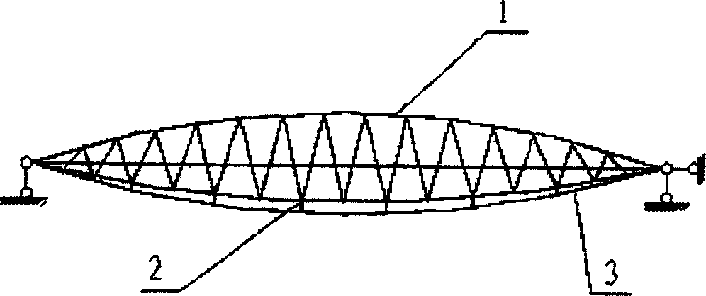
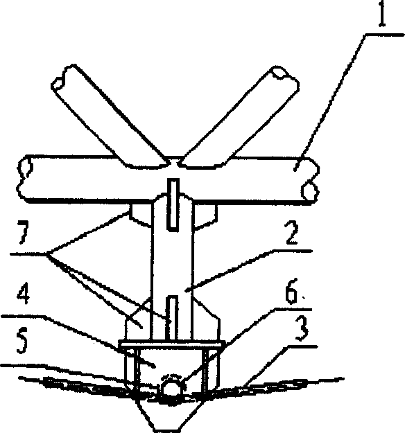
[0025] Embodiment 1 of the present invention: as figure 1As shown, it uses a shuttle-shaped truss (1) as the frame body, and welds a row of vertical short braces (2) with a length of 0.3m to 2.0m on the lower chord of the shuttle-shaped truss (1). The distance between the rods (2) is controlled within 1 to 2 pitches of the shuttle truss (1), and a shaft frame (4) is welded at the lower part of each vertical short strut (2). Stiffeners (7) are welded between the axle frame (4) and each vertical short strut (2) and between each vertical short strut (2) and the shuttle truss (1). Load onto two rolling bearings (5) on the axle frame (4), and all load onto an axle (5) on the rolling bearing (5), open arc groove in the center of axle (5), wire cable (3) respectively attached to the grooves of each shaft (5), and then use the support nodes at both ends of the shuttle truss (1) and the top nodes of each vertical short strut (2) as the supports for the steel cables (3) Tension the st...

Embodiment 2

[0026] Embodiment 2 of the present invention: as Figure 8 As shown, the upper part of the shuttle truss (1) is made into a three-dimensional shuttle truss type "beam" in the traditional way earlier, and all the other manufacturing methods are the same as in embodiment 1.

Embodiment 3

[0027] Embodiment 3 of the present invention: as Figure 10 As shown, it uses a shuttle-shaped truss (1) as the frame body, and welds a row of V-shaped diagonal short struts (2) with a length of 0.3m to 2.0m on the lower chord of the shuttle-shaped truss (1). The distance between the vertices of the bottom ends of the V-shaped short struts (2) is controlled within 1 to 2 nodes of the shuttle-shaped truss (1), and a shaft frame is welded at the bottom of each V-shaped short strut (2) (4), between each shaft frame (4) and each short V-shaped oblique brace (2) and between each V-shaped oblique short brace (2) and the shuttle-shaped truss (1) are welded Stiffener (7), load onto two rolling bearings (5) on each axle frame (4), and all load onto a shaft (5) on the rolling bearing (5), open arc in the center of shaft (5) Groove, paste the steel cables (3) on the grooves of each shaft (5) respectively, and then use the two ends of the shuttle truss (1) to support the nodes and the to...


PUM

PropertyMeasurementUnit
Lengthaaaaaaaaaa

Abstract

The present invention is one new kind of short stay rod type tension string truss. The shuttle-shaped truss has serial short stay rods connected rigidly to the nodes in the lower string; shaft bracket with bearing and shaft fixed to the lower ends of the short stay rods, steel cable pressed on the shaft and with two ends fixed to the end seat nodes separately of the shuttle-shaped truss while in its tensile state. There are arced notch in center of the shaft for the steel cable to contact with, and reinforcing boards between the short stay rods and the shuttle-shaped truss and between the short stay rods and the shaft bracket. The short stay rods are 0.3-2.0 m long. The present invention has the advantages of less steel consumption, simple structure, low cost, high performance, easy construction, etc.

Description

Technical field: [0001] The invention relates to a novel short-strut type tension string truss and a manufacturing method thereof, belonging to the technical field of long-span tension string trusses. Background technique: [0002] In the past ten years, there have been more and more buildings with steel structures as the main body in my country. Among them, in large public buildings such as air show buildings, exhibition centers, and dry coal sheds in industrial buildings, the planar form of the buildings is mostly rectangular. For The long-span rectangular planar roof often adopts the tube truss structure and string beam structure. The tube truss structure generally refers to the planar or spatial tube truss structure of the "pseudo-beam" stress system, such as the tube truss structure (column network 18m x 54m) used in the second phase project (135m x 174m) of the Shenzhen Airport Terminal Building, Nanjing The International Exhibition Center (94m×273m), Wenzhou Conventio...

Claims


Application Information

Patent Timeline
IPC IPC(8): E04B1/19
Inventor 马克俭郑涛张华刚
Owner GUIZHOU UNIV
Why Eureka
Try Eureka