

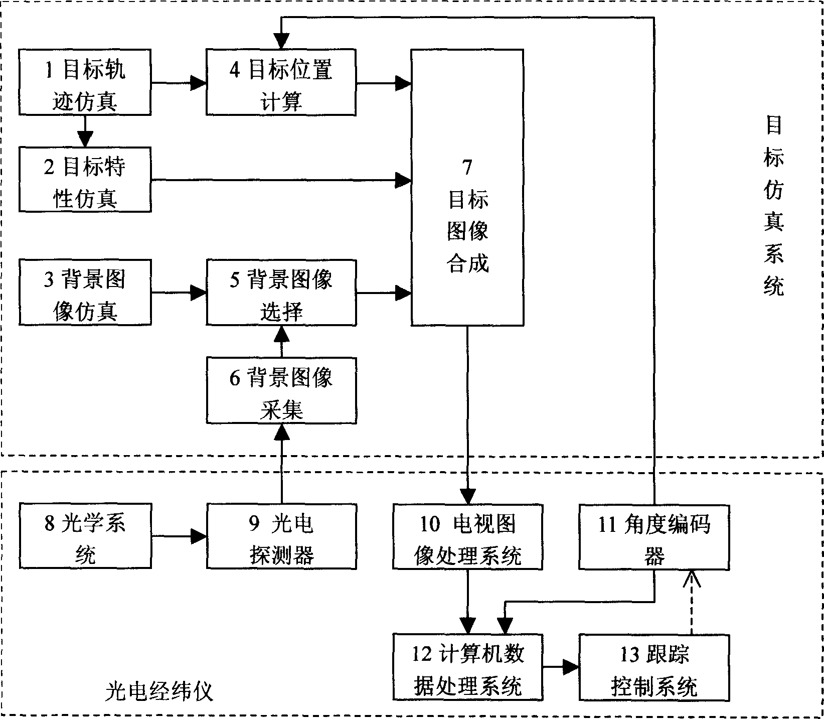
Target simulation method for photoelectric theodolite
A technology of photoelectric theodolite and simulation method, applied in instruments, measuring devices, etc., can solve the problems of high risk, high cost, long cycle, etc., and achieve the effects of simple and convenient operation, short test period, convenience and cost
- Summary
- Abstract
- Description
- Claims
- Application Information
AI Technical Summary
Problems solved by technology
Method used
Image


Examples
Embodiment
[0025] Example: indoor joint debugging of photoelectric theodolite
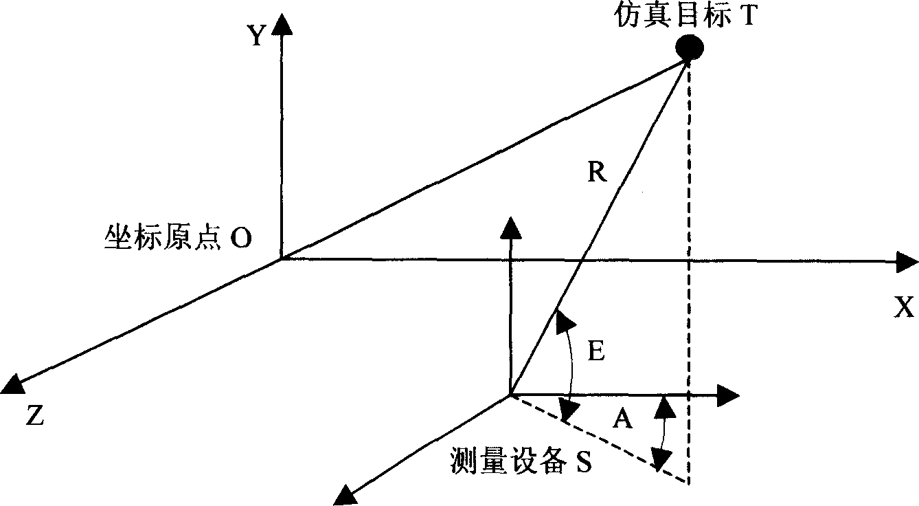
[0026] Such as figure 2 A schematic diagram of a typical missile range measurement is shown. In the figure, O-XYZ is used to establish a unified shooting range Cartesian coordinate system, and the Y axis is vertically upward. The measuring device S photoelectric theodolite is located at (Xs, Ys, Zs) point in this coordinate system. Establish the space polar coordinate system S-RAE with S as the origin, in which the A axis is parallel to the X axis in O-XYZ, and the E zero plane is the O-XZ plane.
[0027] target type
Theoretical point target, white light
target sports
sex
track type
Projectile type, launch from point O, shoot
The direction is the direction of the X axis, and the trajectory is the rationale
On Parabola
Maximum speed
Vmax=1000m / s
launch high angle
45°
acceleration of gravity
9.8m 2 / s
detectors a...
PUM
 Abstract
Description
Claims
Application Information