Check patentability & draft patents in minutes with Patsnap Eureka AI!

Anchor cable stress sensor for optical fiber grating dynamometer

A stress sensor, fiber grating technology, applied in the measurement of fluid pressure, by measuring the change of optical properties of materials when they are stressed, instruments and other directions, can solve problems such as redundancy, and avoid redundancy and organic matter. The effect of easy fatigue decomposition, improved sensing performance and service life

Inactive Publication Date: 2005-06-29
WUHAN UNIV OF TECH
View PDF1 Cites 29 Cited by
  • Summary
  • Abstract
  • Description
  • Claims
  • Application Information

AI Technical Summary

Problems solved by technology

Introducing the fiber optic sensor into the stress ring avoids the disadvantages of the electrical sensor, but the combination of the FBG sensor and the hollow cylindrical part is pasted with an adhesive, which will absorb the stress and cause redundancy

Method used


Image

  • Anchor cable stress sensor for optical fiber grating dynamometer
  • Anchor cable stress sensor for optical fiber grating dynamometer
  • Anchor cable stress sensor for optical fiber grating dynamometer

Examples


Embodiment Construction

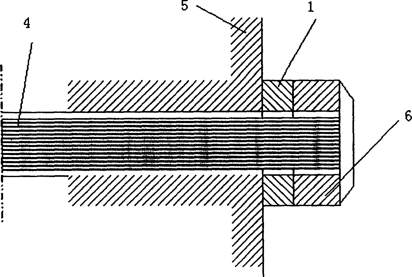
[0014] The fiber grating dynamometer anchor cable stress sensor structure is as follows figure 1. As shown, it includes 1-annular elastic body, 2-fiber grating stress sensor, 3-fiber grating temperature sensor, 8-optical cable outlet seat, 9-optical cable and other parts. Among them, the fiber grating stress sensor and the fiber grating temperature sensor are prepared by glue-free packaging technology; the fiber grating stress sensor, the fiber grating temperature sensor and the annular elastic body are attached by laser spot welding 14, and the welding direction of the fiber grating temperature sensor is perpendicular to the ring The direction of stress on the elastic body. As mentioned above, the fiber grating dynamometer anchor cable stress sensor structure, in which six fiber grating stress sensors 2 are evenly distributed on the outer surface and inner surface of the annular elastic body, are welded by a laser welding machine, and the welding direction is parallel to the ...


PUM


Abstract

This invention is a fiber grating ergometer anchor strain sensor, which comprises ring elastic body, several fiber and grating sensor used in strain measurement and temperature measurement, wherein, the fiber and grating sensor adopts glue-free seal process; the fiber and grating sensor and ring elastic adopts laser points welding; the fiber and grating sensor used in strain measurement evenly stuck to the inner and outer sides of the ring elastic body; the fiber and grating sensor used to measure temperature has a welding direction vertical to the strain of the ring elastic body.

Description

technical field [0001] The invention relates to the stress measurement of the anchor cable in the field of bridge engineering, in particular to the stress measurement of the anchor cable of a dynamometer based on an optical fiber grating. Background technique [0002] Stress rings are widely used in the stress measurement of anchor cables in the fields of civil engineering and bridge engineering. In the prior art, electrical stress sensors are generally used. Electrical stress sensors are easily affected by humidity and temperature to reduce insulation performance, have poor lightning protection, and are prone to generate noise due to the influence of electromagnetic fields, and have poor environmental resistance. Moreover, electrical stress sensors are not suitable for distributed multiplexing structures, and the average cost of each measurement point will increase for multi-point measurement. In addition, the signal-to-noise ratio of the system is not high, and it is diff...

Claims


Application Information

Patent Timeline
IPC IPC(8): E02D5/80G01D21/02G01K11/32G01L1/24G01L19/04
Inventor 姜德生付祥胜梁磊刘胜春南秋明张东生
Owner WUHAN UNIV OF TECH
Features
  • R&D
  • Intellectual Property
  • Life Sciences
  • Materials
  • Tech Scout
  • Unparalleled Data Quality
  • Higher Quality Content
  • 60% Fewer Hallucinations
Learn More