High power microwave power amplifier high-voltage pulse power supply

A high-voltage pulse power supply and microwave power technology, applied in the microwave field, can solve the problems of difficult production, increased volume and weight, etc.

Inactive Publication Date: 2005-07-06
INST OF ELECTRONICS CHINESE ACAD OF SCI
View PDF0 Cites 8 Cited by
  • Summary
  • Abstract
  • Description
  • Claims
  • Application Information

AI Technical Summary

Problems solved by technology

It is more difficult to manufacture when wide pulse output

Method used


Image

  • High power microwave power amplifier high-voltage pulse power supply
  • High power microwave power amplifier high-voltage pulse power supply
  • High power microwave power amplifier high-voltage pulse power supply

Examples


Embodiment Construction

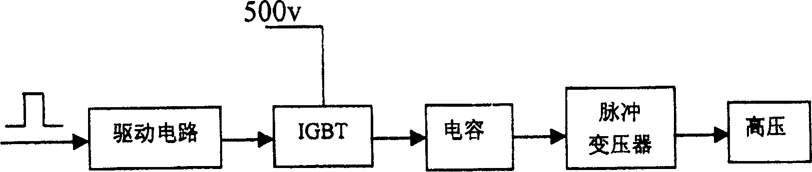
[0014] Such as figure 1 As shown, the high-voltage pulse power supply for a high-power microwave power amplifier of the present invention is composed of a drive circuit, an IGBT (insulated gate bipolar transistor, referred to as IGBT), a capacitor, a pulse transformer, and a solid-state 28v-500v power supply, etc., wherein the drive circuit There are two insulated gate bipolar transistors (IGBT) connected in parallel between the pulse transformer, the output of the drive circuit is connected to the input terminals of the two insulated gate bipolar transistors, and a capacitor is provided between the insulated gate bipolar transistor and the pulse transformer; the insulated gate bipolar transistor The power of the pole transistor (IGBT) is provided by a solid-state 28v ~ 500v power supply.

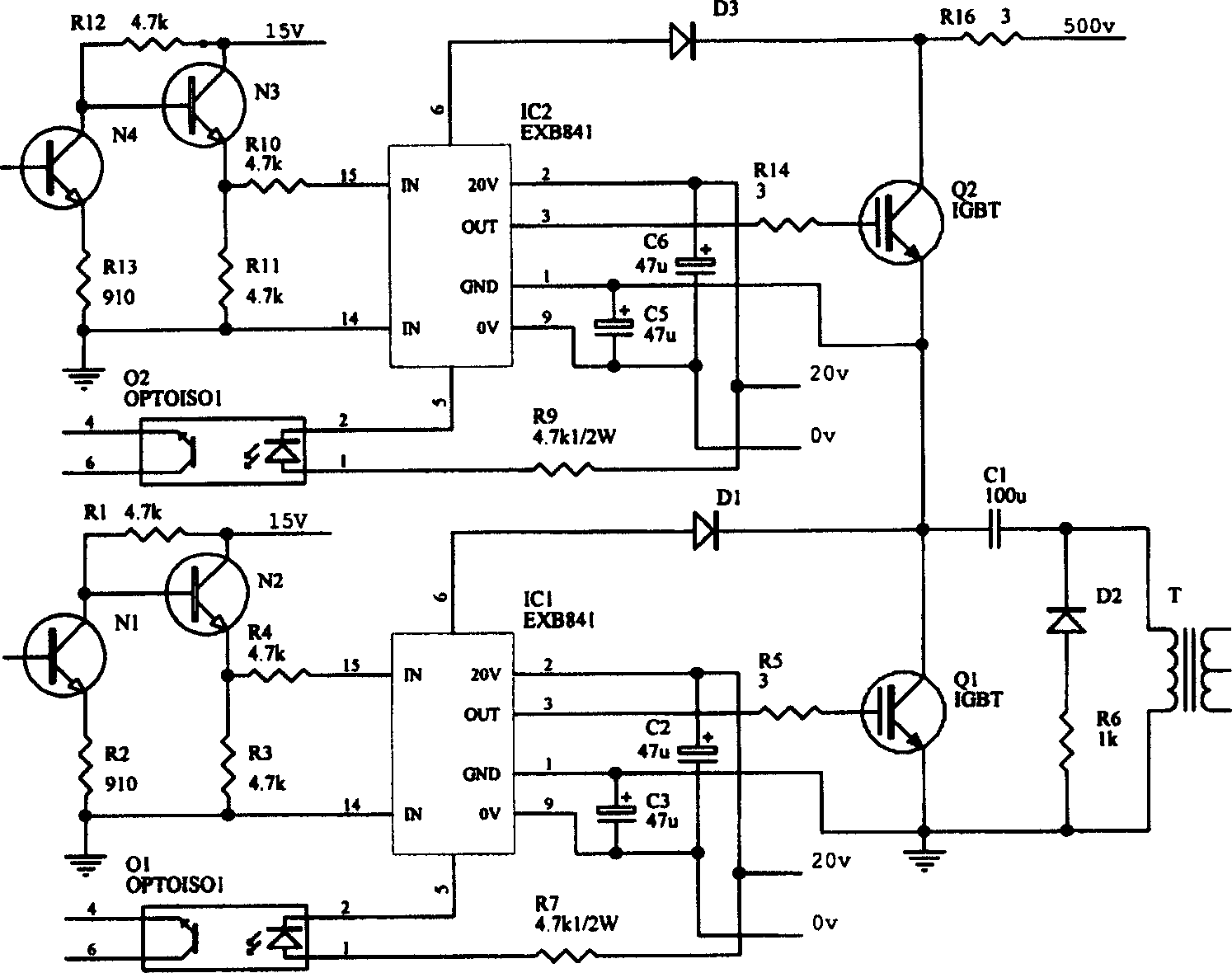
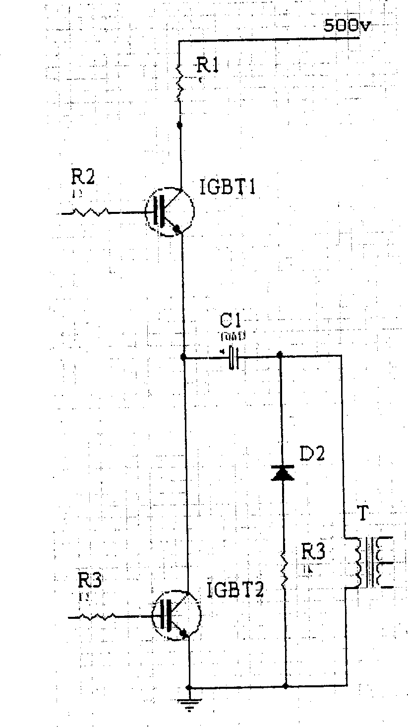
[0015] figure 2 It is the general circuit diagram of the present invention, wherein, the circuit structure of generating pulse part is as image 3 As shown, the 500v power supply is conn...


PUM


Abstract

This invention refers to a high power microwave power amplifier, which contains driving circuit, insulated gate bipolar transistor, capacitor, pulse transformer and solid state power supply, wherein the two insulated gate bipolar transistors are serially connected between driving circuit and pulse transformer, capacitor set between insulated gate bipolar transistor and pulse transformer, insulated gate bipolar transistor is used as the switch of capacitor charge or discharge, high power pulse is generated by the instant discharge of capacitor, the solid state power supply is 28-500v, high voltage power supply is 1000-1600w. Said invention directly generates high power voltage by low voltage power supply for the normal work of klystron and greatly raises power supply efficiency.

Description

technical field [0001] The invention relates to the field of microwave technology, in particular to a high-power microwave power amplifier. technical background [0002] The high-power microwave transmitter uses a klystron as a high-power microwave output element to provide high-power microwave signals to the antenna. When the cathode modulation pulse klystron is used, it needs a high-voltage and high-current switching pulse to modulate the cathode, so that the klystron works in the switching state and outputs microwave pulses at regular intervals. The classic method is to use a hose modulator, which is excited by an artificial line and a hydrogen thyratron to form a switching pulse. After the 3000 volt voltage is boosted to 20,000 volts by a pulse transformer, the high voltage pulse current required by the pulse klystron is provided. . Under the condition that the volume, weight and power consumption are strictly limited, its disadvantage is that the artificial line is re...

Claims


Application Information

Patent Timeline
IPC IPC(8): H03F1/00H03K3/02
Inventor 刘少军杨华光
Owner INST OF ELECTRONICS CHINESE ACAD OF SCI
Why Eureka
Try Eureka