Optical disk, recording and reproducing apparatus for the same, and method for managing address information

A technology of address information and reproducing device, which is applied in the direction of recording information storage, optical recording/reproducing, disc-shaped record carrier, etc., and can solve the problems of bad influence of header signal, high energy density of beam center, influence characteristics, etc.

Inactive Publication Date: 2005-07-13
HITACHT MAXELL LTD
View PDF5 Cites 3 Cited by
  • Summary
  • Abstract
  • Description
  • Claims
  • Application Information

AI Technical Summary

Problems solved by technology

Therefore, the reflectance of the recording layer fluctuates according to the variation in the grain size of the recrystallized region, and this change in reflectivity further adversely affects the header signal.
[0014] When the track pitch is wide, as described above, even if the deterioration of the data signal caused by multiple rewriting occurs, or the recrystallization "band" is formed, their influence on the quality of the header signal is small, but if the track pitch is narrow, they will be significant. Influence characteristics
When blue laser (λ=405nm) is used as the recording laser, the problem of deterioration of header signal quality during multiple rewriting is particularly noticeable
This is probably because the beam diameter of the blue laser is more concentrated compared to the red laser (λ=650nm) used for DVDs, so the energy density at the center of the beam is high, resulting in increased damage caused by repeated rewriting

Method used


Image

  • Optical disk, recording and reproducing apparatus for the same, and method for managing address information
  • Optical disk, recording and reproducing apparatus for the same, and method for managing address information
  • Optical disk, recording and reproducing apparatus for the same, and method for managing address information

Examples


Embodiment 1

[0095] CD

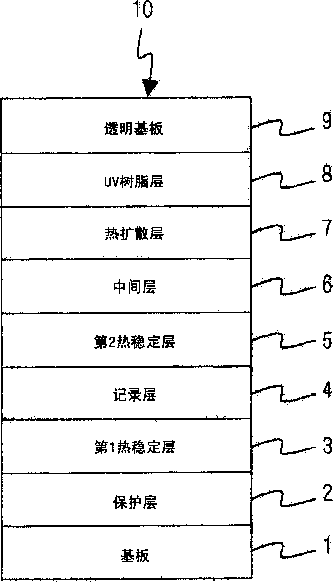
[0096] In Example 1, an optical disc of a phase change recording system was produced. FIG. 1 shows a schematic cross-sectional view of an optical disc produced in this example. As shown in FIG. 1 , the structure of the optical disc 10 produced in this example is that a protective layer 2 , a first thermally stable layer 3 , a recording layer 4 , a second thermally stable layer 5 , and an intermediate layer are sequentially laminated on a substrate 1 . 6. Thermal diffusion layer 7 , UV resin layer 8 and transparent substrate 9 . Next, a method for producing an optical disc of this example will be described.

[0097] First, a substrate 1 made of polycarbonate with a diameter of 120 mm and a thickness of 0.6 mm was produced by injection molding using a press molding machine. At this time, on the substrate 1, grooves (grooves) having a track pitch of 0.34 μm and a depth of 45 nm were formed in the recording area of ​​the optical disc having a radius of 23.8 mm to 58...

Embodiment 2

[0156] In Example 2, various optical discs were produced in the same manner as in Example 1 except that the information recording and reproducing apparatus for measuring the bit error rate was changed, and quality evaluation of address signals and data signals was performed.

[0157] Information recording and reproducing device

[0158] FIG. 5 shows a schematic configuration diagram of an information recording and reproducing apparatus for recording and reproducing information on the optical disc produced in this example. The information recording and reproducing apparatus 200 used in this example is as shown in FIG. The / G servo circuit 13, the reproduction signal processing system 24, and the recording signal processing system 17 are constituted. As can be seen from FIG. 5, the structure of the information recording and reproducing apparatus 200 shown in FIG. 5 is the same as that of the information recording and reproducing apparatus 100 shown in FIG. Configuration of the...

Embodiment 3

[0165] In embodiment 3, except changing the recording format of address information and data information of the optical disc, all the other are produced various optical discs in the same manner as in embodiment 1, and use the information recording and reproducing device shown in Figure 5 to measure the bit error rate as in embodiment 2, and carry out Quality evaluation of address signals and data signals.
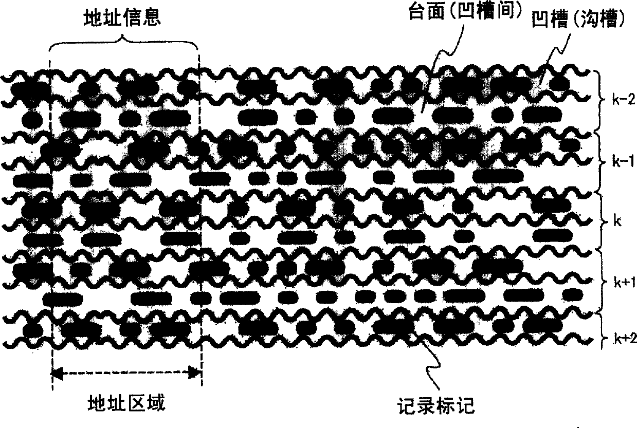
[0166] CD

[0167] FIG. 6 is a schematic diagram showing the recording format of address information and data information of the optical disc produced in this example. In the optical disc of FIG. 6 , data information (recording marks) are recorded on the land, and address information of the track is formed by radially wobbling the groove. In the optical disk of FIG. 6, a set of adjacent grooves and lands is regarded as one track, and the same track number is assigned to the grooves and lands. That is, the address information formed in the groove in the optical disc of FIG...


PUM

PropertyMeasurementUnit
thicknessaaaaaaaaaa
thicknessaaaaaaaaaa
thicknessaaaaaaaaaa

Abstract

An object of the present invention is to provide an optical disc with a large capacity, high reliability, and excellent durability against repeated recording of data information. The optical disc is characterized by: having a substrate formed with a plurality of grooves, and a recording layer provided on the substrate and formed of a phase change material containing Bi, Ge, and Te; the grooves are provided with a recording layer recording the grooves. The header of the groove address information is formed by radially offsetting the groove. The header of each groove is arranged in a radial arrangement, so that even if the address information of a given groove cannot be reproduced , the address information of the groove can also be specifically determined from the address information of adjacent grooves.

Description

technical field [0001] The present invention relates to an optical disc for recording information by irradiating energy beams, its recording and reproducing device, and an address information management method, in particular to an optical disc for recording address information by radially shifting grooves, its recording and reproducing device, and its address information management method . Background technique [0002] In recent years, the market for reproduction-only optical discs such as DVD-ROM (Digital Video Disc-Read Only Memory) and DVD-Video (Digital Video Disc-Video) is expanding. Then DVD-RAM (Digital Video Disc-Random Access Memory) and DVD-RW (Digital Video Disc-Rewritable), DVD+RW (Digital Video Disc+Rewritable) and other rewritable DVD markets are also expanding , This rewritable DVD is rapidly popularized as a file backup medium for computers and an image recording medium to replace VTR (Video Tape Recorder). Accompanied by the expansion of the DVD market, t...

Claims


Application Information

Patent Timeline
Patent Type & Authority Applications(China)
IPC IPC(8): G11B7/00G11B7/007G11B7/09G11B7/243G11B27/24G11B27/30
CPCG11B7/00718G11B7/24082G11B7/243G11B27/24G11B27/3027G11B2007/24312G11B2007/24314G11B2007/24316G11B2220/218G11B2220/2541
Inventor 田村礼仁白井宽饭田保宫本真
Owner HITACHT MAXELL LTD
Why Eureka
Try Eureka