
Optical recording material and optical recording medium

A technology for optical recording media and optical recording materials, applied in the direction of optical recording media, recording carrier materials, optical recording/reproduction, etc., capable of solving problems such as insufficient solubility

Inactive Publication Date: 2005-07-27
TDK CORPARATION
View PDF6 Cites 0 Cited by
  • Summary
  • Abstract
  • Description
  • Claims
  • Application Information

AI Technical Summary

Problems solved by technology

[0007] In addition, when the salts described in JP-A-2000-190641 and JP-A-2000-190642 are used as pigments, the solubility is not sufficient depending on the type of functional group having activated hydrogen.

Method used


Image

  • Optical recording material and optical recording medium
  • Optical recording material and optical recording medium
  • Optical recording material and optical recording medium

Examples


Embodiment 1

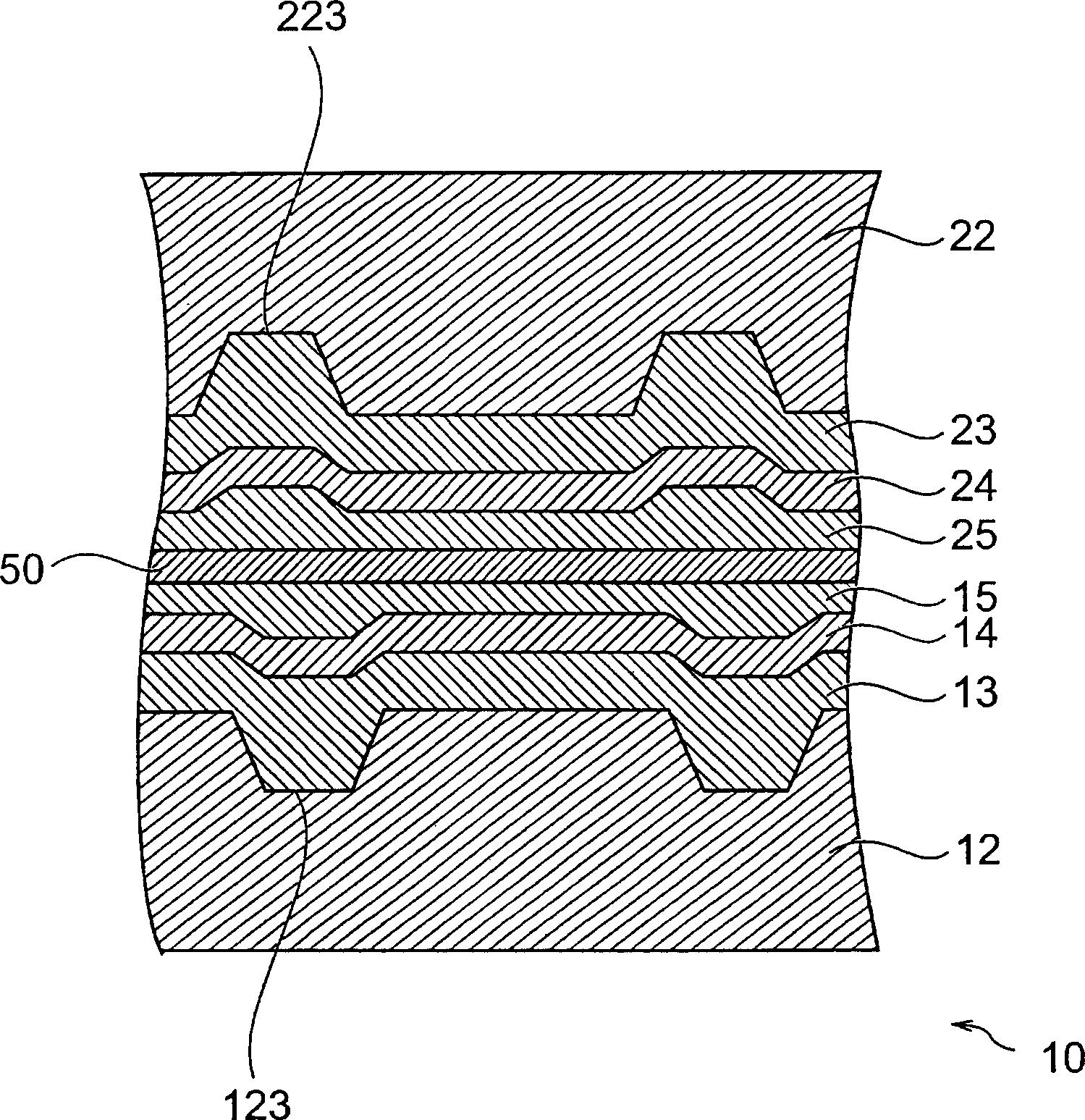
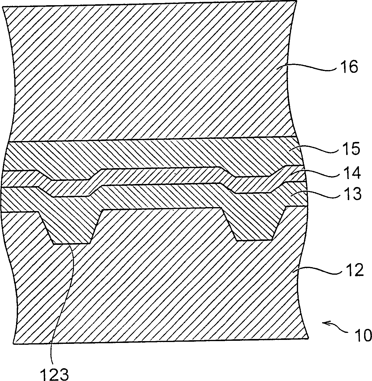
[0126] A polycarbonate resin substrate having a diameter of 120 mm and a thickness of 0.6 mm having pregrooves (180 nm in depth, 0.30 μm in width, and 0.74 μm in pitch) on one side was prepared. Separately, salt-forming dye 1 represented by the following general formula (3) was added to 2,2,3,3-tetrafluoropropanol to prepare a recording layer coating solution having a content of 1.0% by weight.

[0127]

[0128] The obtained coating solution was applied to the surface of the polycarbonate resin substrate on which the pregroove was formed, and dried to form a recording layer (thickness: 100 nm).

[0129] Then, an Ag reflective layer (85 nm thick) was formed by sputtering on the recording layer, and a transparent protective layer (5 μm thick) made of ultraviolet curable acrylic resin was formed on the Ag reflective layer to obtain a laminated structure. Two pieces of this laminated structure are produced, with the protective layer as the inner side, and they are pasted with a...

Embodiment 2

[0131] An optical recording disc was produced in the same manner as in Example 1 except that the salt-forming dye 2 represented by the following general formula (74) was used instead of the salt-forming dye 1 in Example 1.

[0132]

Embodiment 3~13、 comparative example 1~3

[0134] In Examples 3 to 13 and Comparative Examples 1 to 3, optical recording disks were produced in the same manner as in Example 1 except that dye compositions 3 to 13 shown in Table 1 were used instead of salt dye 1, respectively. In Table 1, numbers in parentheses represent symbols of the above-mentioned and following chemical structural formulas.

[0135] Salt

Cyanoin dye

chemical formula

Composition (weight%)

chemical formula

Composition (weight%)

Example 3

(73)

40

(61)

60

Example 4

(73)

50

(61)

50

Example 5

(74)

40

(65)

60

Example 6

(74)

40

(66)

60

Example 7

(74)

40

(67)

60

Example 8

(74)

40

(68)

60

Example 9

(73)

30

(61)

70

Example 10

(73)

60

(61)

40

...


PUM

PropertyMeasurementUnit
diameteraaaaaaaaaa
thicknessaaaaaaaaaa
thicknessaaaaaaaaaa

Abstract

An optical recording material used in an optical recording medium which can record information by light irradiation, this optical recording material containing a dye compound obtained by salt formation between a chelate compound formed by coordination between one metal and one or two compounds represented by the following general formula (1) where A and B are groups of atoms which may be identical or different, and which respectively form aromatic rings, and X<1> and X<2> are respectively functional groups having one or more active hydrogen atoms which may contain a substituent group, and a cation represented by the following general formula (2) where C is a group of atoms forming a benzene ring or naphthalene ring which may have a substituent group, R<1> and R<2> are respectively five-membered rings or six-membered rings which may have a substituent group, Y<1> is a substituent group, Q<3> is a nitrogen-containing heterocyclic ring which may have a condensed ring, p and q are respectively integers from 1 to 4, and n is an integer from 0 to 3.

Description

technical field [0001] The present invention relates to an optical recording material and an optical recording medium used for an optical recording medium for recording information by light. Background technique [0002] In current optical recording media, laser light is generally irradiated to the recording layer, and information is recorded by utilizing shape change, magnetic domain change, phase change, etc. of the recording layer. This type of optical recording medium is widely used, for example, the add-on optical recording medium CD-R disclosed in Japanese Patent Application Laid-Open No. 8-108623 and Japanese Patent Laid-Open No. 8-156408. (add-on disc) and DVD±R (add-on digital video disc), etc. [0003] In recent years, there has been a demand for further densification of optical recording media, and the wavelength of recording-reproducing light has been shortened to meet this demand. For example, the current recording-reproducing light wavelength of CD-R is 780nm...

Claims


Application Information

Patent Timeline
Patent Type & Authority Applications(China)
IPC IPC(8): B41M5/26G11B7/244G11B7/247G11B7/249G11B7/257
CPCG11B7/2467G11B7/2472G11B7/2531G11B7/259G11B7/256G11B7/2575G11B7/2534G11B7/2495G11B7/24038G11B7/2533G11B7/2536G11B2007/24612
Inventor 新海正博门田敦志田边顺志塚本修司洞井高志
Owner TDK CORPARATION
Learn More