Treatment of node area deformation based shear wall

A processing method and node domain technology, applied in the direction of electrical digital data processing, special data processing applications, walls, etc., can solve problems such as waste, structural safety, increase, etc., and achieve the effect of an effective processing method

Inactive Publication Date: 2005-07-27
SHANGHAI JIAO TONG UNIV
View PDF0 Cites 0 Cited by
  • Summary
  • Abstract
  • Description
  • Claims
  • Application Information

AI Technical Summary

Problems solved by technology

The lateral stiffness of high-rise buildings is an important control index. If the lateral stiffness of the structure is too small, it will be necessary to increase the component section or add new components, which will cause unnecessary waste
More importantly, as the building structure is a statically indetermin

Method used


Image

  • Treatment of node area deformation based shear wall
  • Treatment of node area deformation based shear wall
  • Treatment of node area deformation based shear wall

Examples


Embodiment 1

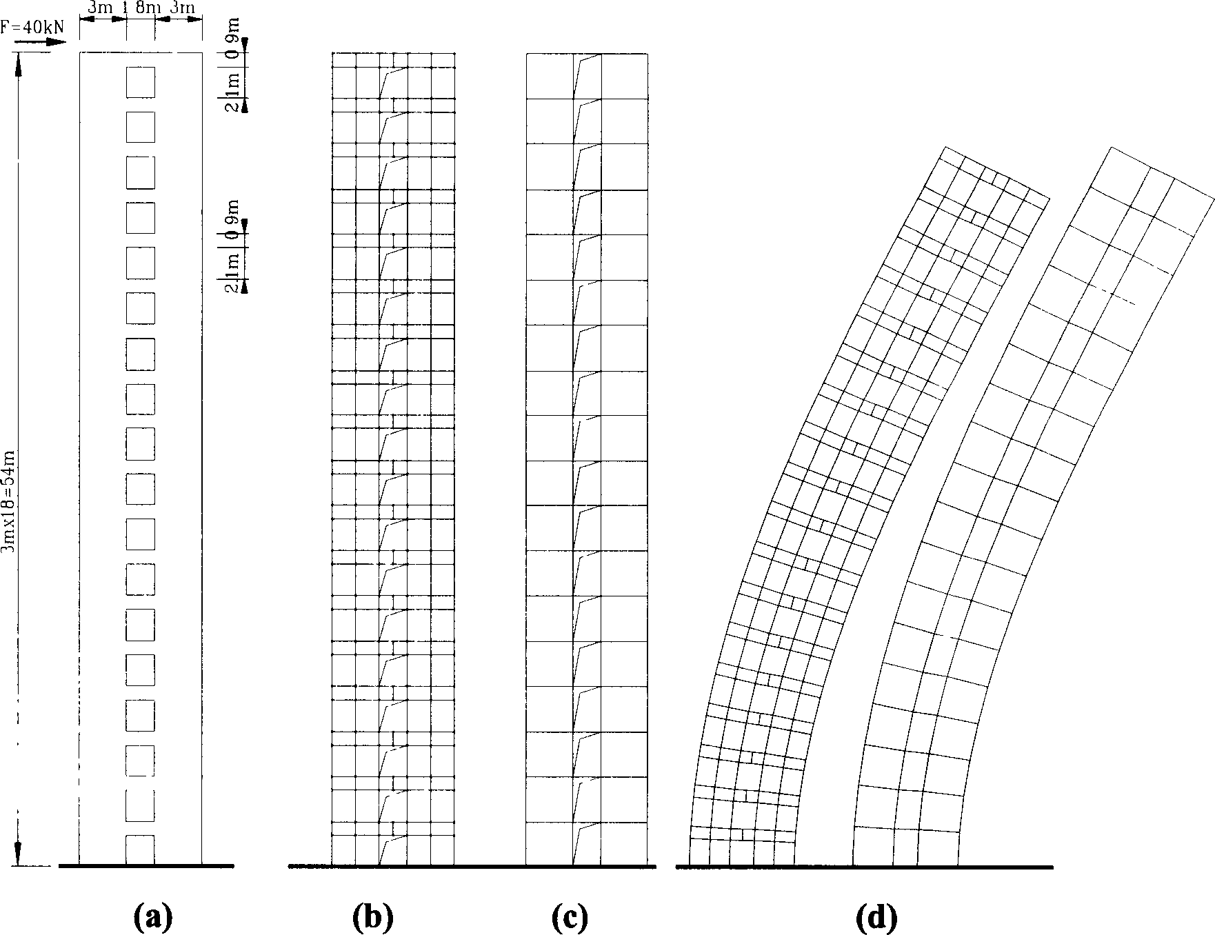
[0061] Such as figure 2 Shown is a typical planar jointed shear wall structure with 18 floors, 3m height, and 54m total height. The wall pier has a cross-section length of 3m. Due to the opening of doors and windows on the wall, the connecting beam is 1.8m long and the cross-section height is 0.9m. The simulated structure is subjected to lateral wind load, and the horizontal thrust P=40kN is applied on the top. Analyze the top side displacement of the structure, and the force of the wall limbs and connecting beams.

[0062] The wall limbs in the structure are processed by the method of the present invention. In order to compare the performance of the wall element of the present invention, different processing modes are adopted for the connecting beams:

[0063] 1) The connecting beam is simulated by wall elements, such as figure 2 As shown in (b), the corresponding wall limbs are subdivided;

[0064] 2) The coupling beam is simulated by beam element, such as figure 2 As shown i...

Embodiment 2

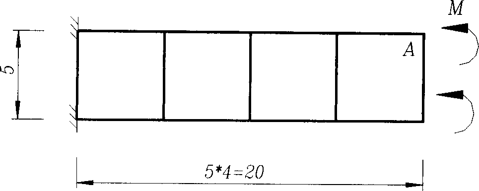
[0072] Such as image 3 Cantilever structure shown. The cell size is 5×5, the thickness is 1, E=3000, μ=0.25. Apply the end node concentrated bending moment M=5, analyze the end face rotation angle, and the end node rotation angle.

[0073] In order to better reflect the performance of the wall element of the present invention, other publicly issued commercial software was used to calculate the structure at the same time, and the results are shown in Table 2.

[0074] The "end face rotation angle" in the table is the average cross section angle obtained by dividing the longitudinal displacement difference of the two points at the end by the length of the end face. "Point A corner" is the corner of the node itself.

[0075] Software

A point corner

Error

End section corner

Error

ANSYS

0.5410

8353.13%

0.0064

0.00%

SAP84

0.0227

254.69%

0.0064

0.00%

SATWE

0.01075

68.00%

0.006...

Embodiment 3

[0080] In order to better and intuitively reflect the performance of the wall element under the action of concentrated bending moment, in the previous embodiment image 3 Based on the foundation, an overhanging beam is added at the end node position, the beam length is 5, the section height is 1.5, and the thickness is the same as the cantilever wall. Concentrated force P=10 is applied to the end of the outrigger. Such as Figure 4 Shown. Calculate the beam end deformation and compare it with the theoretical results of the wall frame. The results are shown in Table 3.

[0081] Software

Beam end side shift

Error

SAP84

2.4347

144.03%

[0082] SATWE

1.0920

9.45%

ETABS

1.5143

51.78%

this invention

1.0209

2.33%

Wall frame

0.9977

[0083] This structure not only reflects the performance of the wall element under the action of the concentrated bendin...


PUM


Abstract

A method for treating the shear wall based on the deformation of node domain includes such steps as using the 12 node elements of the parallelogram with variable side point position as the basic unit of wall element, generating the rigidity of corner in wall element plane according to the concept of node domain deformation, and determining the distance from side point to unit coordinate axis to treat the centralized bending moment's action domain of node.

Description

Technical field [0001] The invention relates to a method for processing a shear wall in civil construction, in particular to a method for processing a shear wall based on the deformation of a node domain. It belongs to the technical field of civil engineering and construction. Background technique [0002] Shear wall is an important component in civil engineering, and both concrete and steel-concrete hybrid high-rise structures adopt shear wall as the main lateral force-resistant component. Shear walls, beams and columns and other components form a structural force system, which bears structural loads. In structural finite element analysis, shear walls are generally simulated by wall elements (also called shell elements), and beams and columns are simulated by beam-column elements. In order to mix the wall element with the beam-column element and effectively calculate the force of the civil building structure, it is necessary for the wall element to have in-plane corner freedom a...

Claims


Application Information

Patent Timeline
IPC IPC(8): E04B2/00G06F17/50
Inventor 谢靖中
Owner SHANGHAI JIAO TONG UNIV
Why Eureka
Try Eureka