Large pneumatic equipment blades made of composite material and production thereof

A technology of wind turbine blades and composite materials, which is applied in the directions of wind turbines, wind turbine components, mechanical equipment, etc., can solve the problems of increasing the expenditure of special equipment and increasing the cost of blade manufacturing.

Inactive Publication Date: 2005-07-27
TONGJI UNIV
View PDF1 Cites 28 Cited by
  • Summary
  • Abstract
  • Description
  • Claims
  • Application Information

AI Technical Summary

Problems solved by technology

[0005] The problem that arises from this is that the keel beam must be continuous, almost equal to the length of the blade
These have all increased the special equipment expenditure in the manufacture of blade, improved the manufacturing cost of blade

Method used


Image

  • Large pneumatic equipment blades made of composite material and production thereof
  • Large pneumatic equipment blades made of composite material and production thereof
  • Large pneumatic equipment blades made of composite material and production thereof

Examples


Embodiment 1

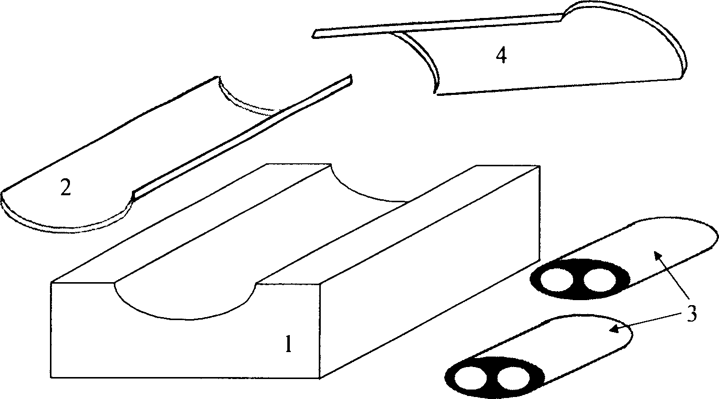
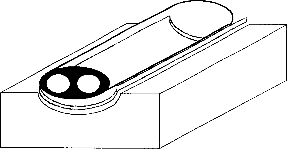
[0030] The metal (aluminum alloy, titanium alloy, stainless steel, etc.) connector 7 passes through the solid wooden keel frame 5, wherein the cross-sectional shape of the metal passing section is square, and is fastened with gaskets and nuts at the other end of the keel frame, see hint image 3 , the shape of the keel frame is consistent with the cross-sectional shape of the blade root. The length of the solid keel frame (the direction indicated by the arrow) is limited, no more than 0.5m. All the other sections of the keel frames 8 are hollow wooden structures, made of wooden splints and battens, and have an appropriate length. After all these keel frames are connected end to end, the similar shape of the blade to be prepared must be formed. The laying of the fiber cloth in the lower cavity 1 is shown in the cross section Figure 5 : Pre-impregnated (medium temperature curing resin, curing temperature 60°-100°) multi-layer carbon fiber woven cloth 9, braiding angle 10°-20...

Embodiment 2

[0032] Embodiment 2 is basically the same as Embodiment 1, but each fiber cloth (i.e. carbon fiber cloth 9, glass fiber cloth 11, nylon cloth 12) is no longer divided into two pieces (see schematic diagram Figure 5 10) in , but weave into schematic Figure 6 Cylindrical shape shown in 13. The leaves were prepared in the same manner as described in Example 1.

Embodiment 3

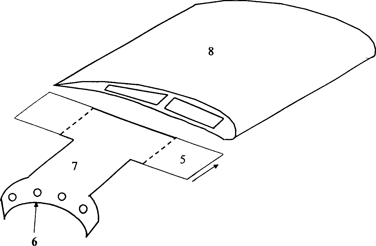
[0034] Embodiment 3 is basically the same as Embodiment 1, but some inner layer fiber cloths are pressed Figure 7 As shown in the preparation, wherein 14 is a carbon fiber cloth, 15 is a nylon cloth, which are sewn together into one. The use of this composite fiber cloth is convenient to realize the change of the thickness of the blade shell along the section circumference as required. Due to the airfoil shape of the blade section, the force-bearing area is on the windward side, while the force on the other side sheltered from the wind is relatively small. Therefore, the optimally designed composite blades not only have different cross-sectional shapes, but also have different shell thicknesses in the same cross-section: thicker on the windward side and thinner on the sheltered side. application Figure 7 As shown in the fiber cloth, the purpose can be achieved by arranging the nylon cloth on the sheltered side.


PUM


Abstract

A big-scale composite wind turbine blade characterized by once molding with entwined fiber as the strengthened materials and its fabricating method. The blade is composed by enhanced fiber, resin base, keel and couplings. The glue dipped fiber is put in a stair way in the lower blade mold, whereon the keels conjunct to each other and the keel on the rear part of the blade conjunct to the coupling. The cross section of the keels is similar to that of the blade. Correspondingly another layer of the glue dipped fiber is put in a stair way in the upper blade mold. The two parts of the blade mold are closed, sealed, vacuumed, injected into resin, heated to solidify and removed in steps to get the wind turbine blade.

Description

technical field [0001] The invention relates to wind turbine blades, in particular to a large composite material wind turbine blade and a preparation method thereof. Background technique [0002] Due to the increasing shortage of primary energy (petroleum, coal, etc.), the development and utilization of renewable energy has become the consensus of mankind and has attracted great attention from all countries. Among them, wind energy is a kind of renewable energy with the most commercial development value at present, and it will surely become a focus of energy development and utilization in our country. [0003] Wind power generation is to collect scattered wind energy to do mechanical work, and then convert it into electrical energy, so that it can be directly used by human beings. Blades play a pivotal role in wind turbines. The design and manufacturing quality level of the blade is the key technology and technical level representative of the wind power generation system. ...

Claims


Application Information

Patent Timeline
Patent Type & Authority Applications(China)
IPC IPC(8): B29C45/14F03D80/00
CPCY02E10/722Y02E10/72Y02P70/50
Inventor 黄争鸣
Owner TONGJI UNIV
Why Eureka
Try Eureka