Quantum lattice diffracting rasters

A diffraction grating and quantum dot technology, applied in the field of diffraction gratings, can solve problems such as errors, reflection holographic grating reflectivity cannot be guaranteed, diffraction grating interference, etc., to avoid interference and errors, eliminate advanced diffraction, and improve monochromatic performance.

Active Publication Date: 2005-07-27
LASER FUSION RES CENT CHINA ACAD OF ENG PHYSICS
View PDF0 Cites 15 Cited by
  • Summary
  • Abstract
  • Description
  • Claims
  • Application Information

AI Technical Summary

Problems solved by technology

The amplitude and phase of the transmission holographic grating change sinusoidally, which still leads to the existence of advanced diffraction ("Engineering Optics", Mechanical Industry Press, edited by Yu Daoyin and Tan Hengying), the reflectivity of the reflective holographic grating cannot be guaranteed to change sinusoidally , will also lead to the existence of high-order diffraction
Advanced diffraction brings interference and errors to the application of diffraction gratings, for example: 1. The spectrum obtained when the grating is used as a spectrometer splitting element is the superposition of the first-order spectrum and each advanced spectrum, which cannot directly reflect the shape of the actual spectrum; 2. When the grating is used as a monochromator, the light obtained at the exit will contain a certain amount of high-order harmonic components

Method used


Image

  • Quantum lattice diffracting rasters
  • Quantum lattice diffracting rasters
  • Quantum lattice diffracting rasters

Examples


Embodiment 1

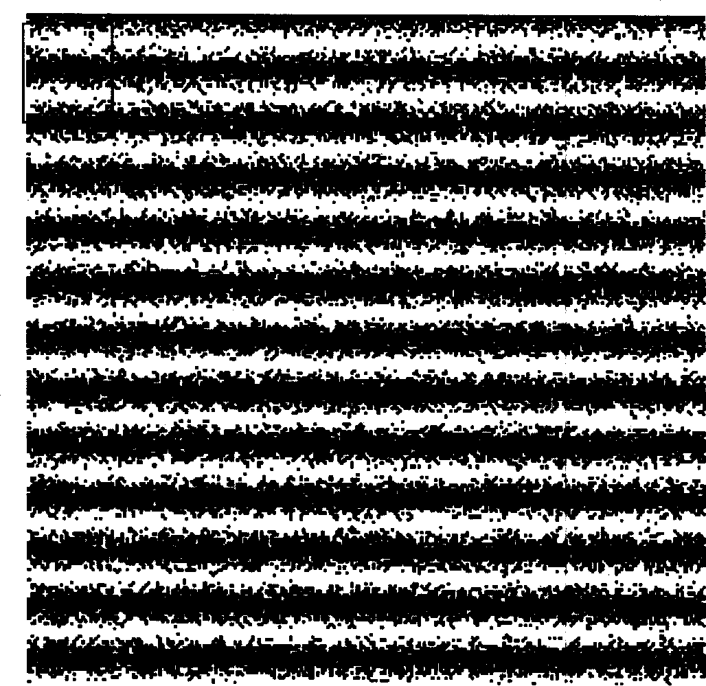
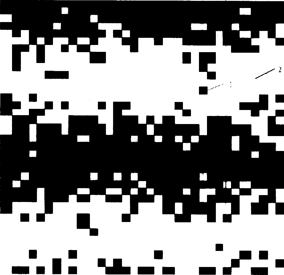
[0034] figure 1 It is a square quantum dot array plane transmission diffraction grating according to an embodiment of the present invention.

[0035] The preparation process of the embodiment of the present invention is:

[0036] ① First of all, using computer-aided design methods, based on the formula ρ N (x)=(1 / 2+1 / 2cos(πx / d))d produces figure 1 The square quantum dot array plane transmission diffraction grating pattern shown, where ρ N Is the number density of quantum dots, x is a certain dimensional coordinate on the surface of the grating substrate, and d is the period length of the sinusoidal change. The size of quantum dots is much smaller than d, at least 1 / 5 of d.

[0037] ②. Convert the square quantum dot array plane transmission diffraction grating pattern generated in ① into LEDIT format file;

[0038] ③Using CNC focused electron beam lithography equipment, controlled by the LEDIT file generated in step ②, will be as figure 1 The square quantum dot array plane tran...

Embodiment 2

[0041] The quantum dot array plane transmission diffraction grating obtained in Example 1 was used as the X-ray lithography mask, and the quantum dot array plane transmission diffraction grating was obtained by using X-ray lithography technology to replicate. The quantum dot material was gold, and the transparent substrate surface material was used. CH material.

Embodiment 3

[0043] Preparation of the inverse grating of the quantum dot array diffraction grating.

[0044] By the transfer method, the same material as in Example 1 or Example 2 is used to produce a pattern structure opposite to that in Example 1 or Example 2, and the inverse grating of the quantum dot matrix diffraction grating can be made. The diffraction pattern of the inverse grating is the same as the diffraction pattern of Example 1 or Example 2.


PUM


Abstract

A diffraction grating of quantum dot array is prepared by arranging large amount of quantum dots in quasi-random way on grating base, placing dots on one dimensional space of surface is random distribution and on another dimensional space in sine distribution for obtaining quantum dot array grating. The senior diffraction of the grating is so low as to be ignored.

Description

1. Technical Field [0001] The present invention relates to the field of diffraction gratings, in particular to a quantum dot matrix diffraction grating used as a spectrometer beam splitting element or a monochromator wavelength separation / selection element, and to an inverse grating made by transferring from the quantum dot matrix diffraction grating And copy the raster. 2. Background technology [0002] A diffraction grating is a collection of reflective (or transmissive) optical elements whose distance from each other is equivalent to the wavelength of the light to be studied. It can be seen as a series of diffractive elements such as a series of slits (or holes) on an opaque screen, or a collection of a series of reflective grooves on a substrate. A reflection grating is composed of a grating superimposed on a reflective surface, and a transmission grating is composed of a grating superimposed on a transparent surface. The electromagnetic wave incident on the grating, through ...

Claims


Application Information

Patent Timeline
Patent Type & Authority Applications(China)
IPC IPC(8): G02B5/18
Inventor 曹磊峰
Owner LASER FUSION RES CENT CHINA ACAD OF ENG PHYSICS
Why Eureka
Try Eureka