Comprehensive measuring method and circuit for electric motor rotating speed and rotor location

A technology of rotor position and motor speed, applied to devices using electric/magnetic methods, motor generator testing, electronic commutators, etc., can solve large measurement errors, encoder pulse sequences are no longer evenly spaced, and cannot be measured Problems such as motor rotors, to eliminate errors, reduce hardware configuration, and improve measurement accuracy

Inactive Publication Date: 2005-07-27
浙江大学三伊电气电子工程公司
View PDF0 Cites 26 Cited by
  • Summary
  • Abstract
  • Description
  • Claims
  • Application Information

AI Technical Summary

Problems solved by technology

[0006] The conventional M/T measurement method is only used to measure the speed of the motor, and cannot measure the position of the motor rotor while measuring the speed
In addition, large-scale units will generate axial and radial vibrations during o

Method used


Image

  • Comprehensive measuring method and circuit for electric motor rotating speed and rotor location
  • Comprehensive measuring method and circuit for electric motor rotating speed and rotor location
  • Comprehensive measuring method and circuit for electric motor rotating speed and rotor location

Examples


Embodiment Construction

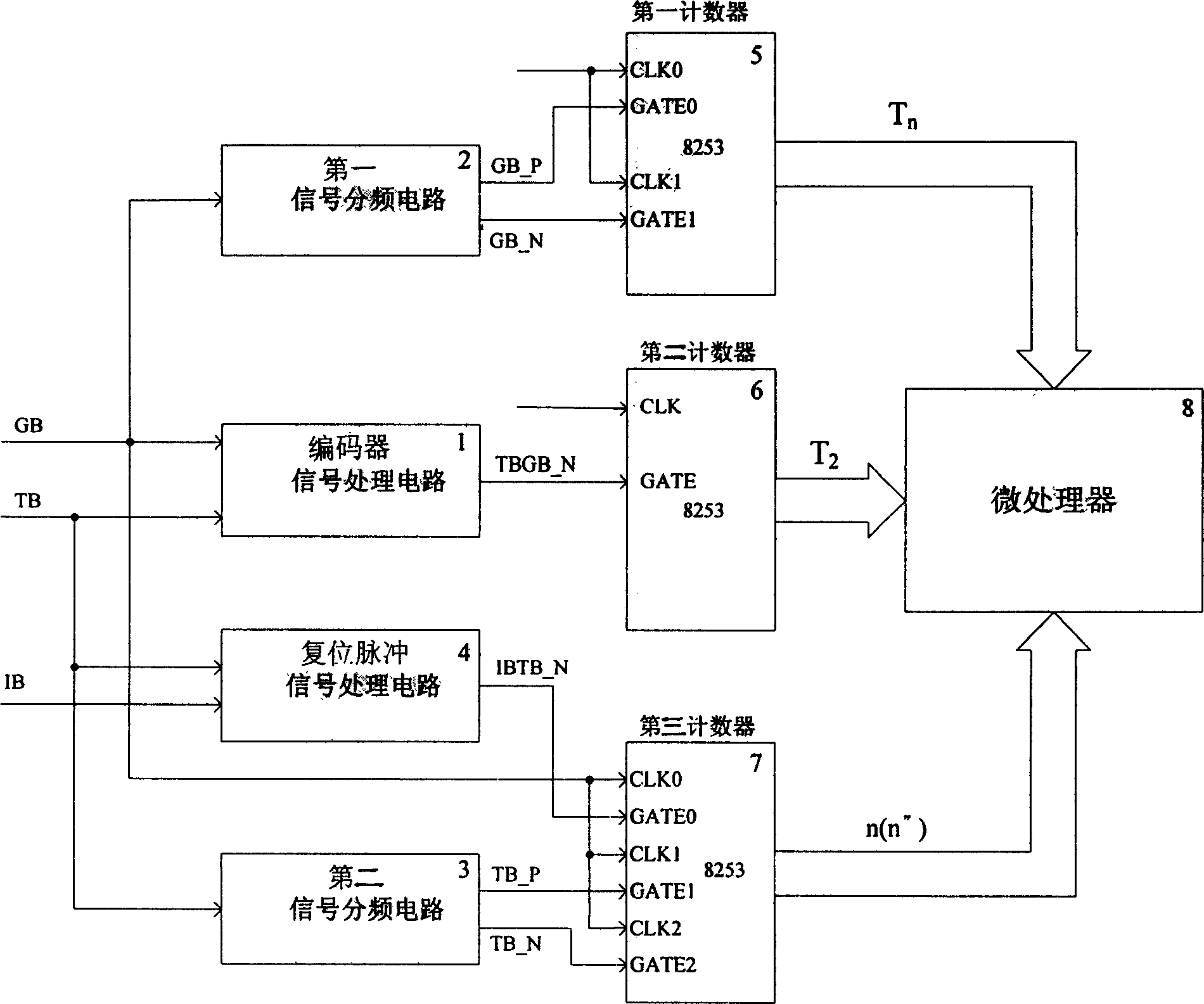
[0041] Reference figure 1 , The measurement circuit used in the integrated measurement method of motor speed and rotor position of the present invention includes an encoder signal processing circuit 1, a first signal frequency dividing circuit 2, a second signal frequency dividing circuit 3, a reset pulse signal processing circuit 4, The first counter 5, the second counter 6, the third counter 7 and the microprocessor 8, an input terminal of the encoder signal processing circuit 1 and the input terminal of the first signal frequency dividing circuit 2 and the clock terminal of the third counter 7, respectively Connect the pulse signal GB output by the encoder, the other input terminal of the encoder signal processing circuit 1 and the input terminal of the second signal frequency dividing circuit 3 and one input terminal of the reset pulse signal processing circuit 4 are respectively connected to the given measurement period pulse Signal TB, the other input terminal of the reset ...


PUM


Abstract

The method gets the periodic signal and compound signal of encoder through processing the pulse signal, reset signal from encoder and measurement period signal given by measuring man. By using the formula raised by the invention, the MPU can figure out the rotate speed of motor and the position of rotor. The invention can also remove the measuring error for motor caused by radial and axial vibration.

Description

Technical field [0001] The invention relates to a method for measuring the rotation speed and rotor position of an AC motor and a measuring circuit. Background technique [0002] With the development of microelectronics technology, the computing power and reliability of digital control processing chips have been greatly improved. Therefore, in the high-precision AC motor speed control system, fully digitalized with single-chip microcomputer or DSP as the control core is widely used. Control System. In the motor closed-loop feedback control system, the speed and rotor position are two important physical quantities, and their measurement accuracy will directly affect the performance of the control system. [0003] The photoelectric encoder installed on the motor shaft is usually used as the measuring element of the motor speed and rotor position. When the motor rotates, the encoder outputs a digital pulse signal, which is introduced to two counters, one of which counts the encoder ...

Claims


Application Information

Patent Timeline
IPC IPC(8): G01D5/244G01P3/42G01R31/34H02P6/00H02P6/16
Inventor 程方斌赵荣祥蔡慧杨欢钱昊汪世平周军伟陈坚吴靖
Owner 浙江大学三伊电气电子工程公司
Why Eureka
Try Eureka