Method for controlling pulley homing in optic disc machine
A technology of optical disc drives and pulleys, which is applied in optical recording/reproduction, recording of information on magnetic disks, instruments, etc., and can solve problems such as improving optical disc drives, increasing hardware components, production costs, and machine parts damage. To achieve the effect of improving the failure rate
- Summary
- Abstract
- Description
- Claims
- Application Information
AI Technical Summary
Problems solved by technology
Method used
Image

Examples
Embodiment Construction
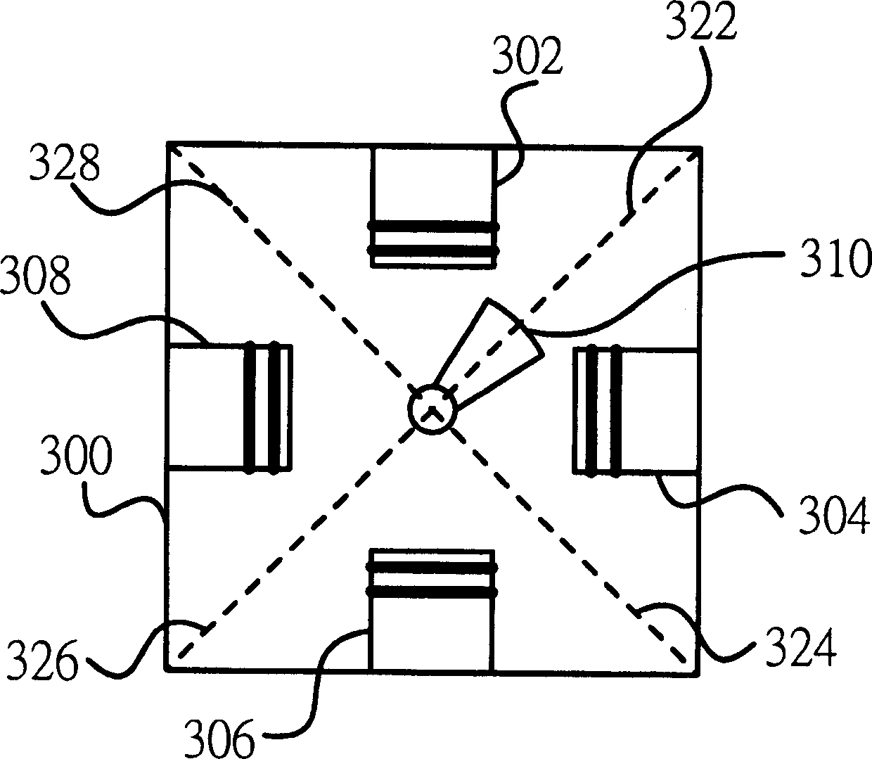
[0019] Referring to Fig. 3, it is a schematic diagram of a stepping motor, used to illustrate the control method of the stepping motor 300, the stepping motor is used as the pulley motor as described above, which includes a rotor 310, a phase A stator 302, a phase B stator 304, a phase A' stator 306, and a phase B' stator 308, wherein the rotor 310 has a specific magnetic field, so the protruding end of the rotor in the figure will point to a rotor direction in the same direction as the applied magnetic field ; while the individual stator can change the direction of the individual magnetic field through an external control signal, and synthesize an equivalent magnetic field direction to control the direction of the rotor. Referring to Fig. 4 again, it is a timing diagram for illustrating the control signal of the stepping motor to control the excitation frequency of the stepping motor, wherein the control signal of each phase is switched between a high potential and a low poten...
PUM
 Abstract
Description
Claims
Application Information
 - Generate Ideas
- Intellectual Property
- Life Sciences
- Materials
- Tech Scout
- Unparalleled Data Quality
- Higher Quality Content
- 60% Fewer Hallucinations
Browse by: Latest US Patents, China's latest patents, Technical Efficacy Thesaurus, Application Domain, Technology Topic, Popular Technical Reports.
© 2025 PatSnap. All rights reserved.Legal|Privacy policy|Modern Slavery Act Transparency Statement|Sitemap|About US| Contact US: help@patsnap.com