Self adaptive frequency domain receiver for super broad band radio communication system and receiving method

A wireless communication system, self-adaptive technology, applied in the field of communication, can solve the problems of strict timing control, low interception rate, and increased complexity, and achieve the effects of avoiding delay branch circuits, good receiving performance, and low complexity

Active Publication Date: 2005-08-03
BEIJING UNIV OF POSTS & TELECOMM +1
View PDF0 Cites 16 Cited by
  • Summary
  • Abstract
  • Description
  • Claims
  • Application Information

AI Technical Summary

Problems solved by technology

Moreover, the transmission power of UWB is very small, even lower than the noise emitted by ordinary equipment, so it has a very low interception rate
[0003] UWB usually uses Gaussian pulses with a pulse width of tens of picoseconds for communication, and the pulse spans a wide range of frequency bands. According to the Nyquist sampling criterion, to restore the signal, it is required to sample the signal at a sampling rate of tens of G. The current The level of chip design is difficult to achieve
In addition, due to the large attenuation of the outdoor atmosphere when the UWB signal is transmitted outdoors, it is mainly used for indoor high-speed short-distance transmission; because the indoor channel environment is more complex, it will produce reflection, diffraction and refraction of the UWB signal and other phenomena, which cause the diffusion of signal energy and serious multipath fading. Under the condition of severe multipath fading, a signal g(t) of 1 nanosecond may spread into a signal of tens to hundreds of nanoseconds, but Since the transmitted UWB signal width is very narrow (usually up to tens of picoseconds), it has good multipath resolution ability, and the Rake receiver can be used at the receiving end to combine multipath energy. The Rake receiver of the UWB system Schematic diagram such as figure 1 As shown, but the use of rake receiver also brings a problem that the performance of the rake receiver is related to the number of energy paths that can be collected. The more the number of multipaths collected, the better the performance, so the multipath fading of UWB signals is serious As a result, Rick receiving with a large number of branches is required to achieve good performance
However, the use of multiple rake branches leads to an increase in the complexity of the system design, so most of the current rake receivers suitable for UWB systems use partial rake combining, that is, combining the paths with the strongest energy
This partial rake receiver structure has better performance in the energy-concentrated channel environment, but when the multipath energy is scattered, the performance will deteriorate sharply
[0004] As mentioned above, currently used UWB receivers push the existing CMOS technology to the limit and consume huge power, so the existing UWB receivers usually process the received signal with analog correlators using silicon germanium technology, which is It is very difficult to realize a low-power, low-power UWB system in a full CMOS chip
[0005] In order to increase the sampling rate of analog-to-digital conversion, a parallel sampling structure is usually used to sample the signal. However, the parallel sampling structure requires many parallel ADCs, and they have strict requirements on the timing control of the parallel ADCs, and the time offset Shifting is very sensitive. For UWB systems, in order to achieve a sampling rate of several G, the timing control of parallel structure sampling should be accurate for 10-10 seconds. The schematic diagram of signal sampling is as follows figure 2 As shown, this is difficult to achieve in design, but in fact, parallel sampling does not really reduce the complexity of sampling, and it is rarely used in actual occasions that require high sequential logic control

Method used


Image

  • Self adaptive frequency domain receiver for super broad band radio communication system and receiving method
  • Self adaptive frequency domain receiver for super broad band radio communication system and receiving method
  • Self adaptive frequency domain receiver for super broad band radio communication system and receiving method

Examples


Embodiment Construction

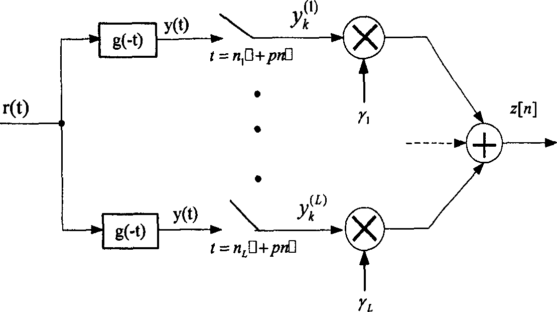
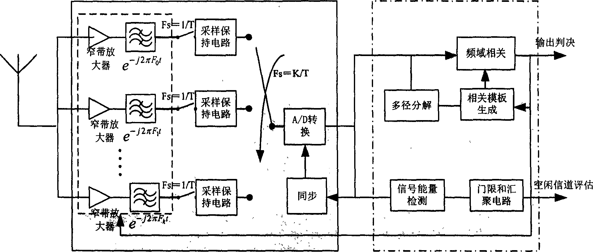
[0027] The invention discloses a new adaptive UWB receiving structure based on frequency-domain signal processing. Compared with other receiver structures, the receiver structure of the invention avoids the technical difficulties of UWB receiving system design, and can adopt very low The sampling rate samples the received signal, and all digital signal processing is in the frequency domain, which greatly reduces the complexity and power consumption of UWB chip design and implementation, and its performance is not much different from traditional high-complexity receivers . Among them, the design of the adaptive filter and the generation of the relevant reference template signal in the frequency domain are the keys to the design of the receiver structure.

[0028]According to the basic idea of ​​the present invention, the frequency domain receiver of the present invention proposes a new technical solution based on the technical difficulties faced by the UWB receiver introduced i...


PUM


Abstract

This invention discloses an adaptive frequency domain receive method used in a super-wide-band radio communication system using a band-pass filter set, among which, difference of central frequencies of adjacent filters is a fixed frequency interval and the central frequency of each band-pass filter is adjusted adaptively by feedback including: every filter gets the spectrum information of related frequency point signal in received signals, after filtering the filers with the symbol frequency of the received signal, the signal from sampling is converted in module to get a set of frequency domain digital signals, maximum likelihood estimation is carried out to the digital signal and the current local formwork signals to get new local formwork signals to be correlated with the digital signal to get the sent information.

Description

technical field [0001] The invention relates to the field of communication technology, in particular to an adaptive frequency domain receiver structure and a receiving method based on frequency domain signal processing applied to an ultra-wideband system. Background technique [0002] Ultra-WideBand (Ultra-WideBand) is an emerging wireless communication technology. It has received extensive attention due to its low power consumption, wide bandwidth, and simple design. It has become a research hotspot in recent years. It is a wireless personal area network WPAN The most competitive alternative proposal. Since the ultra-wideband system occupies a very wide frequency band, it brings great challenges to the radio frequency and digital signal processing of the receiving system. In the current two UWB implementation schemes DS-CDMA and MB-OFDM, the MB-OFDM scheme adopts OFDM technology. On the contrary, the original intention of UWB pulse communication is deviated from. In the im...

Claims


Application Information

Patent Timeline
IPC IPC(8): H04B1/69
Inventor 张平陶小峰张新跃崔琪楣
Owner BEIJING UNIV OF POSTS & TELECOMM
Why Eureka
Try Eureka