
Non-grid ion plating aide

A plating aid and ion technology, applied in ion implantation plating, ion beam tube, sputtering plating, etc., can solve the problems of reduced roughness, increased refractive index, and reduced water absorption, and achieves easy anode replacement , good quality, easy to disassemble and assemble

Inactive Publication Date: 2005-09-14
HONG FU JIN PRECISION IND (SHENZHEN) CO LTD +1
View PDF1 Cites 2 Cited by
  • Summary
  • Abstract
  • Description
  • Claims
  • Application Information

AI Technical Summary

Problems solved by technology

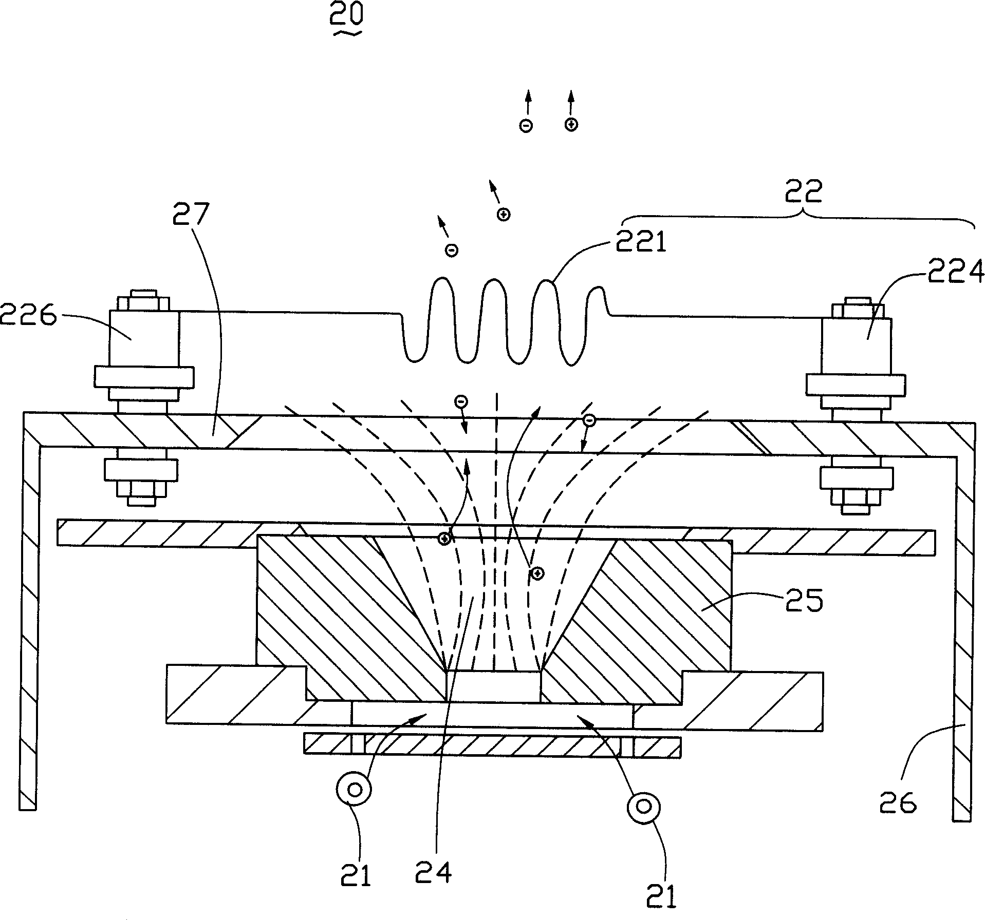
[0006] The impact of ion-assisted plating on the growing film atoms can make the spectral characteristics of the film particularly stable, reduce water absorption, increase refractive index and reduce roughness. This is because the film packing density increases after ion-assisted plating, and the film becomes denser. Therefore, the amount of water absorption becomes less, the spectral characteristics will not drift, and the refractive index becomes larger and more stable. However, the anode of the above-mentioned ion-assisted plating device is a cone-shaped structure with an upward opening, and the angle of ion emission cannot be accurately controlled so that it can be accurately hit on the surface. on the substrate, thus affecting the control of coating quality

Method used


Image

  • Non-grid ion plating aide
  • Non-grid ion plating aide

Examples


Embodiment Construction

[0019] The present invention will be further described in detail below with reference to the drawings and embodiments.

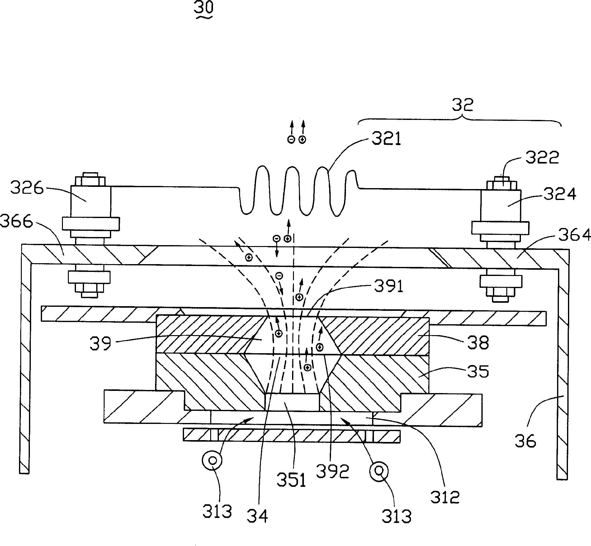
[0020] See figure 2 , A gridless ion plating aid of the present invention includes: an ion source 30, the ion source 30 includes: a discharge area 34 (also called a discharge chamber); a magnetic circuit 36, the magnetic circuit 36 ​​surrounding the Discharge area 34; a gas supply system (not labeled); an anode 35 arranged below the discharge area 34; a cathode 32 arranged above the discharge area 34, corresponding to the anode 35; and an anode emitting The angle workpiece 38 is arranged above the anode 35 for controlling the ion emission angle.

[0021] The magnetic circuit 36 ​​of the present invention is arranged around the gridless ion booster, and is generally composed of a back magnetic pole (not labeled), a magnet (not labeled), an outer magnet (not labeled), and top magnets 364 and 366. The back magnetic pole (not labeled), magnet (not labeled), outer ma...


PUM


Abstract

The invention relates to a non-grid ion coating aided machine for vacuum filming device. It includes an ion source which includes a discharge zone and magnetic circuit located in the zone; a gas supplying system; an anode located under the discharge zone; a cathode located on the discharge zone that corresponding to the anode; and an anode launch angle workpiece located on the anode and is used to control the ion launch angle. The invention would improve the filming quantity of the basis material.

Description

【Technical Field】 [0001] The invention relates to a vacuum coating equipment, in particular to a gridless ion plating aid. 【Background technique】 [0002] Traditional vacuum coating equipment uses resistors or electron beams to heat the film material to the evaporation temperature under vacuum conditions to evaporate and deposit on the substrate to form a thin film to achieve the purpose of coating. However, the energy of the atoms of the film to be evaporated is low, the adhesion of the film layer is poor, and the density is low. The properties of the film are greatly affected by the environment, easy to fall off, and unstable. In addition, when the electrons evaporate, the grid voltage of the electron gun is 6000-10000V, which is easy to cause high-voltage discharge and ignition, which affects the quality of the film. [0003] In order to increase the adhesion and density of the vacuum coating and improve its physical properties, an ion source is used to bombard the substrate d...

Claims


Application Information

Patent Timeline
Patent Type & Authority Applications(China)
IPC IPC(8): C23C14/46H01J27/02H01J27/14
Inventor 颜士杰
Owner HONG FU JIN PRECISION IND (SHENZHEN) CO LTD
Learn More