

Life refuse incinerator
A domestic waste incineration and furnace body technology, which is applied in the field of incinerators, can solve the problems of unstable combustion of garbage in the furnace, failure to achieve various indicators of combustion, and secondary pollution of the environment, and achieve the goal of reducing harmful gases such as dioxins Effects of generation, improvement of ventilation and ignition process, and reduction of furnace construction costs
- Summary
- Abstract
- Description
- Claims
- Application Information
AI Technical Summary
Problems solved by technology
Method used
Image

Examples
Embodiment 1
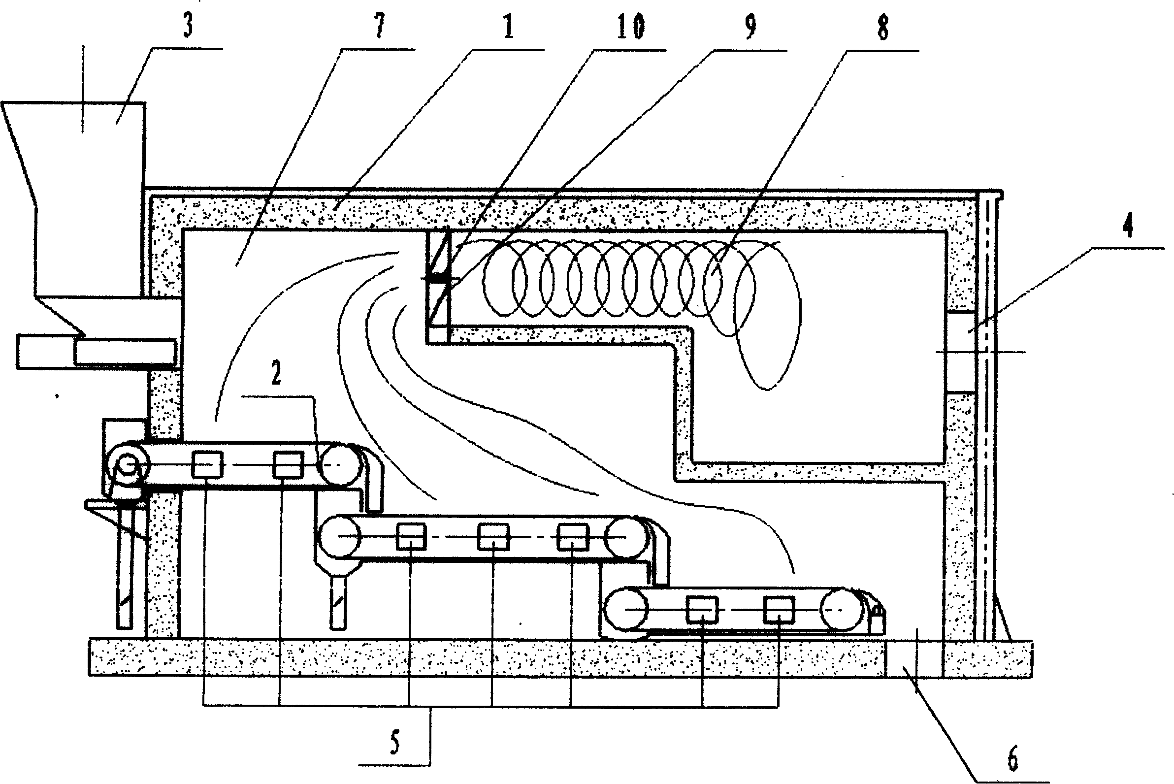
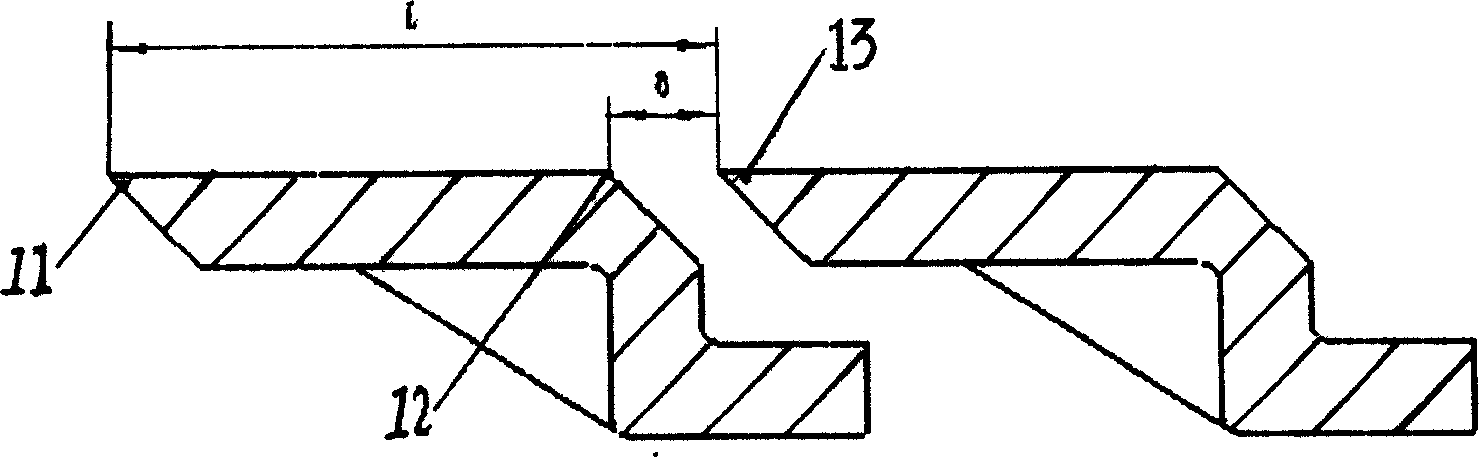
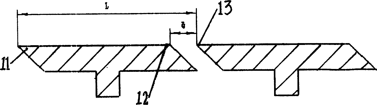
[0011] Such as figure 1 The shown garbage incinerator includes a furnace body 1 and a grate assembly 2. The furnace in the furnace body 1 is divided into a first combustion chamber 7 and a second combustion chamber 8. The second combustion chamber 8 is in front of the first combustion chamber 7. The smoke inlet 9 of the second combustion chamber 8 is located at the top of the first combustion chamber 7, and a swirl device 10 is installed on the smoke inlet 9. The first combustion chamber 7 is a three-section flat arch, and the grate assembly 2 is in the first combustion chamber, which is divided into three parts: the drying area, the burning area, and the burning area. The slag inlet 3 is above the rear part of the furnace body 1 , the smoke outlet 4 is located in front of the second combustion chamber 8 , and the lower part of the furnace body 1 is an air inlet 5 and a slag outlet 6 . Such as figure 2 The shown grate, between two adjacent grate pieces 11, the installation ...
Embodiment 2
[0014] Such as figure 1 The shown garbage incinerator includes a furnace body 1 and a grate assembly 2. The furnace in the furnace body 1 is divided into a first combustion chamber 7 and a second combustion chamber 8. The second combustion chamber 8 is in front of the first combustion chamber 7. The smoke inlet 9 of the second combustion chamber 8 is located at the rear upper part of the first combustion chamber 7, and a swirl device 10 is installed on the smoke inlet 9. The first combustion chamber 7 is a three-section flat arch, and the grate assembly 2 is in the first combustion chamber, which is divided into three parts: the drying area, the burning area, and the burning area. The slag port 3 is behind the upper part of the furnace body 1 , the smoke outlet 4 is located in front of the second combustion chamber 8 , and the lower part of the furnace body 1 is an air inlet 5 and a slag outlet 6 . Such as figure 2 The shown grate, between two adjacent grate pieces 11, the ...
Embodiment 3
[0017] Such as figure 1 The shown garbage incinerator includes a furnace body 1 and a grate assembly 2. The furnace in the furnace body 1 is divided into a first combustion chamber 7 and a second combustion chamber 8. The second combustion chamber 8 is in front of the first combustion chamber 7. The smoke inlet 9 of the second combustion chamber 8 is located at the rear upper part of the first combustion chamber 7, and a swirl device 10 is installed on the smoke inlet 9. The first combustion chamber 7 is a three-section flat arch, and the grate assembly 2 is in the first combustion chamber, which is divided into three parts: the drying area, the burning area, and the burning area. The slag inlet 3 is at the rear of the upper part of the furnace body 1 , the smoke outlet 4 is located in front of the second combustion chamber 8 , and the lower part of the furnace body 1 is an air inlet 5 and a slag outlet 6 . Such as figure 2 The shown grate, between two adjacent grate pieces...
PUM
 Abstract
Description
Claims
Application Information